Installation Instructions Removing and Replacing the Line Interface Module Internal Components Catalog Numbers 2094-AL15S, 2094-AL25S, 2094-AL50S, 2094-AL75S, 2094-BL10S, 2094-BL25S, 2094-BL50S, 2094-BL75S, 2094-XL75S-C1, 2094-XL75S-C2, 2094-AL09, 2094-BL02 About This Publication Topic Page About This Publication 1 Important User Information 2 Catalog Number Explanation 3 Field Replaceable Components 4 Remove/Replace the Front Cover 5 Remove the Circuit Breakers 7 Replace the Circuit Break
Removing and Replacing the Line Interface Module Internal Components Important User Information Solid state equipment has operational characteristics differing from those of electromechanical equipment. Safety Guidelines for the Application, Installation and Maintenance of Solid State Controls (publication SGI-1.1 available from your local Rockwell Automation sales office or online at http://literature.rockwellautomation.
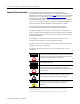
Removing and Replacing the Line Interface Module Internal Components Catalog Number Explanation Cat. No. Line Interface Module (LIM) catalog numbers and descriptions are listed in the table below. Input Voltage Current Rating 2094-AL15S 15 A 2094-AL25S 25 A 2094-AL50S 230V 50 A 2094-AL75S 75 A 2094-BL10S 10 A 2094-BL25S 2094-BL50S 3 460V 2094-BL75S 25 A 50 A Description • 230V ac auxiliary power output. • Customer-configurable branch-circuit protection.
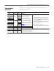
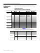
Removing and Replacing the Line Interface Module Internal Components Field Replaceable Components This section provides descriptions and catalog numbers for the field-replaceable components internal to the Line Interface Module. Field Replaceable Components (2094-ALxxS, 2094-BLxxS, and 2094-XL75S-Cx LIM modules) Cat. No.
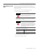
Removing and Replacing the Line Interface Module Internal Components Remove/Replace the Front Cover 5 To perform all component removal/replacement procedures, you need to remove power from the unit and remove the front cover to gain access to the internal components. There are no tools needed to remove the front cover. Follow these steps to remove the LIM module front cover. 1. Remove all input power to the LIM module.
Removing and Replacing the Line Interface Module Internal Components 6. Locate the two bail fasteners (lower front cover) and rotate them one quarter turn in either direction. Line Interface Module, Front View (2094-AL09 module is shown) MAIN VAC Closed AUX VAC BRAKE-I/O VAC Open Bail Fasteners 7. Slide the cover away and down from the LIM module. Line Interface Module, Right-side View (2094-AL09 module is shown) 8. To replace the LIM module front cover, reverse steps 6 and 7.
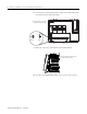
Removing and Replacing the Line Interface Module Internal Components Remove the Circuit Breakers 7 You will need a flat-blade screwdriver to remove circuit breakers. Follow these steps to remove LIM module circuit breakers. 1. Verify that all power is removed from the LIM module as described in Remove/Replace the Front Cover on page 5. 2. Locate the Main VAC (CB1), Control VAC (CB2), and Brake - I/O (CB3) circuit breakers and Fuse Block (FB1).
Removing and Replacing the Line Interface Module Internal Components Locating CB3, FB1, CB2A, and CB2 (2094-BLxxS) CB3 FB1 CB2 (assembly) WIRE_10 WIRE_9 COIL_A2 WIRE_7 WIRE_2 WIRE_1 WIRE_15 WIRE_X3 WIRE_X4 1 3 5 2 4 6 1 3 2 4 Fuse access compartments (pull down to open) 12 14 11 1 3 2 4 WIRE_16 WIRE_3 WIRE_4 WIRE_19 WIRE_18 WIRE_X1 WIRE_X2 Brake and I/O (24V ac) Fuse Block Line Interface Module (2094-BLxxS module is shown) Control VAC (CB2) Auxiliary Contact (CB2A) IMPORTANT
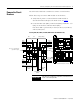
Removing and Replacing the Line Interface Module Internal Components 9 Locating CB1, CB2_AUX, CB2, and CB3 (2094-AL09) CB1 CB2 CB3 AUXSTAT_1 WIRE_2 L3 WIRE_6 WIRE_7 L2 WIRE_8 WIRE_9 WIRE_1 L1 1 3 5 1 3 5 1 3 2 4 6 2 4 6 2 4 WIRE_14 WIRE_16 WIRE_3 WIRE_4 WIRE_5 WIRE_13 WIRE_15 AUXSTAT_2 Line Interface Module (2094-AL09 module is shown) 230VAC_L1 230VAC_L2 Control VAC Brake and I/O (24V ac) (CB2) Main VAC (230/460V ac) Auxiliary Contact (CB2_AUX) Locating CB1, CB2_AUX, CB2, a
Removing and Replacing the Line Interface Module Internal Components 3. Remove wiring from the top and bottom circuit breaker terminals and label each wire if not already done. 4. Using a flat-blade screwdriver, release the spring latch beneath each circuit breaker while pulling the breaker up and away from the DIN rail. 13.0 mm (0.51 in.) Removing/inserting wires Releasing the spring latch (1) (1) Replace the Circuit Breakers Turn screw clockwise to tighten, counter-clockwise to loosen.
Removing and Replacing the Line Interface Module Internal Components Remove the Auxiliary Contact 11 You will need a flat-blade screwdriver to remove the CB2A auxiliary contact from the CB2 control circuit breaker. IMPORTANT This procedure applies to only the auxiliary contact in 2094-ALxxS, 2094-BLxxS, and 2094-XL75S-Cx LIM modules. Other LIM modules do not have an auxiliary contact. Follow these steps to remove the auxiliary contact. 1.
Removing and Replacing the Line Interface Module Internal Components Replace the Auxiliary Contact You will need a flat-blade screwdriver to replace the CB2A auxiliary contact with the CB2 control circuit breaker. For replacement component part numbers, refer to the tables on page 4. IMPORTANT This procedure applies to only the auxiliary contact in 2094-ALxxS, 2094-BLxxS, and 2094-XL75S-Cx LIM modules. Other LIM modules do not have an auxiliary contact.
Removing and Replacing the Line Interface Module Internal Components Replace the (FB1) Fuses 13 No tools are required to replace FB1 fuses. TIP IMPORTANT It is not necessary to remove the LIM module front cover to access FB1 fuses. This procedure applies only to 2094-ALxxS, 2094-BLxxS, or 2094-XL75S-Cx LIM modules. There are no field replaceable fuses in other LIM modules. Follow these steps to replace FB1 fuses. 1.
Removing and Replacing the Line Interface Module Internal Components 2. Determine your ease of access to the cooling fan. If access to the fan is Then Limited (insufficient clearance to access fan screws) Remove the LIM module from the cabinet (1) before proceeding to step 3. Not limited (adequate clearance to access fan screws) Go to step 3. (1) For drive system component removal/replacement procedures, refer to the appropriate servo-drive user manual in Additional Resources on page 21. 3.
Removing and Replacing the Line Interface Module Internal Components Replace the Cooling Fan 15 You will need a #2 phillips screwdriver to replace the cooling fan. Follow these steps to replace the LIM cooling fan. 1. Verify that all power is removed from the LIM module as described in Remove/Replace the Front Cover on page 5. 2. Connect the replacement fan to the power cord and place the fan back inside the LIM module.
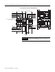
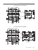
Publication 2094-IN009C-EN-P — April 2008 IPL OPL 4 3 J4 P4 L1 L1 L2 L2 L3 4 Pin 1 Pin 2 Pin 3 Pin 4 PE L3 L2 L1 ALRM_COM L2 IPL: VAC LINE L1 3 PE L3' L2' L1' 2 1 IPL Pin 1 Pin 2 Pin 3 Pin 4 OPL: VAC LOAD B CR1 1 2 N/C 12 22 32 42 54 M 2 4 1 3 FB1 2 4 3 CB 3 ALRM_M 1 ALRM_B 3 5 1 CB1 (Bulletin 140U) AL 1c 4 6 5 2 3 1 4 6 A2 1 L1 L2 L3 N 1 2 3 4 6 7 8 9 10 L1' L2' L3' N' PE Three-phase, 1-Stage Line Filter (460VAC) 4 3 12 1 LF 2 CB 2 14 2 11 53 A
IPL OPL 4 3 2 1 4 3 2 1 Pin 1 Pin 2 Pin 3 Pin 4 IPL: VAC LINE 4 3 2 1 IPL Pin 1 Pin 2 Pin 3 Pin 4 OPL: VAC LOAD PE L3' L2' L1' J4 P4 L3 L1 L1 L2 L2 B CR1 2 N/C 12 22 32 42 54 PE L3 L2 L1 ALRM_COM L3 L2 L1 M 2 4 1 3 FB1 ALRM_B 1 ALRM_M 1 TX1 6 4 2 3 5 2 4 6 1 3 5 CB 3 460V :: 230V 750VA CB1 (Bulletin 140U) AL 1c 5 3 1 4 6 A2 1 L1 L2 L3 N 1 2 3 4 6 7 8 9 10 L1' L2' L3' N' PE Three-phase, 1-Stage Line Filter (460VAC) 4 3 12 1 LF 2 CB 2 14 2 11
Publication 2094-IN009C-EN-P — April 2008 APL IPL OPL 2 1 4 3 2 1 4 3 2 1 J4 P4 1 B CR1 1 2 N/C 12 22 32 42 54 PE L3 L2 L1 APL: AUXILIARY PWR INPUT Pin 1 L2/N Pin 2 L1 2 1 APL Pin 1 Pin 2 Pin 3 Pin 4 L1 L1 L2/N L2/N ALRM_COM 4 IPL: VAC LINE L3 3 L1 L2 2 1 IPL Pin 1 Pin 2 Pin 3 Pin 4 M 3 1 FB1 4 2 4 6 3 5 ALRM_M 1 ALRM_B 2 CB 3 6 4 2 3 5 1 CB1 (Bulletin 140U) AL 1c 5 3 4 6 A2 1 53 L1 L2 L3 N 1 2 3 4 6 7 8 9 10 L1' L2' L3' N' PE Three-phase
IPL OPL 1 2 3 4 1 2 3 4 PE L3' L2' L1' Pin 1 Pin 2 Pin 3 Pin 4 PE L3 L2 L1 IPL: VAC LINE INPUT Pin 4 Pin 3 Pin 2 Pin 1 OPL: VAC LOAD OUTPUT L3_IN L2_IN L1_IN 5 L3 L2 L1 LF2 L2' L2 5 4 6 5 21 22 3 4 2 11 12 2 CB2_AUX CB2 CB3 1 2 1 3 1 3 4 31 32 41 42 PE L2 L1 PE L2 L1 CONSTAT_11 CONSTAT_21 CONSTAT_31 PS1 2 A Power Supply PS2 6 A Power Supply D1 COIL_A1 CONSTAT_41 A1 A2 24- 24+ 24- 24+ MBRK_COM MBRK_PWR IO_COM IO_PWR L2/N L1 COIL_A2 C
Publication 2094-IN009C-EN-P — April 2008 IPL OPL 4 3 2 1 4 3 2 1 PE L3' L2' L1' Pin 4 Pin 3 Pin 2 Pin 1 L3_IN L2_IN L1_IN 5 Cooling Fan LF2 L2' L2 FAN_2 FAN_1 L3 L2 L1 LF1 PE L3' L2' L1' Three-phase, 1-Stage Line Filter (460VAC) CR1 100S-C85 5 6 3 4 5 6 4 31 32 3 21 22 2 CB2_AUX CB2 CB3 4 2 11 12 1 3 1 1 2 41 42 PE L2 L1 PE L2 L1 CONSTAT_11 CONSTAT_21 CONSTAT_31 PS1 2 A Power Supply PS2 6 A Power Supply D1 COIL_A1 CONSTAT_41 A1 A2 C
Removing and Replacing the Line Interface Module Internal Components Additional Resources 21 These documents contain additional information concerning related Rockwell Automation products. Resource Description Kinetix 2000 Multi-axis Servo Drives User Manual, publication 2093-UM001 Mounting, wiring, setup with RSLogix 5000 software, applying power, and troubleshooting information with appendices to support firmware upgrades and common bus applications.
Removing and Replacing the Line Interface Module Internal Components Notes: Publication 2094-IN009C-EN-P — April 2008
Removing and Replacing the Line Interface Module Internal Components 23 Notes: Publication 2094-IN009C-EN-P — April 2008
Rockwell Automation Support Rockwell Automation provides technical information on the Web to assist you in using its products. At http://support.rockwellautomation.com. you can find technical manuals, a knowledge base of FAQs, technical and application notes, sample code and links to software service packs, and a MySupport feature that you can customize to make the best use of these tools.