
Installation Instructions Instruction Manual

16 Kinetix 6200 and Kinetix 6500 IAM and AM Power Modules
Rockwell Automation Publication 2094-IN011D-EN-P - August 2013
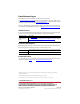
IAM/AM Module Power Wiring Requirements
ATTENTI ON: To avoid personal injury and/or equipment damage, make sure installation
complies with specifications regarding wire types, conductor sizes, branch circuit protection,
and disconnect devices. The National Electrical Code (NEC) and local codes outline provisions
for safely installing electrical equipment.
ATTENTI ON: To avoid personal injury and/or equipment damage, make sure motor power
connectors are used only for connection purposes. Do not use them to turn the unit on and
off.
ATTENTI ON: To avoid personal injury and/or equipment damage, make sure shielded power
cables are grounded to prevent potentially high voltages on the shield.
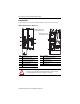
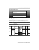
IAM/AM Module
Cat. No.
Description
Terminals Recommended
Wire Size
mm
2
(AWG)
Strip
Length
mm (in.)
Torque Value
N•m (lb•in)
Pin Signal
2094-BC01-Mxx-
M
2094-BC02-M02-M
2094-BMP5-M
2094-BM01-
M
2094-BM02-
M
Motor power
MP-4
MP-3
MP-2
MP-1
Motor power cable depends on
motor/drive combination.
6…1.5
(10…16)
10 (0.38)
0.5…0.6
(4.4…5.3)
2094-BC04-M03-
M
2094-BM03-M
10…1.5
(8…16)
10 (0.38)
1.2…1.5
(10.6…13.2)
2094-BC07-M05-
M
2094-BM05-M
30…2.5
(3…14)
16 (0.63)
2.4…3.0
(21.6…26.5)
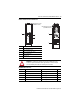
2094-BCxx-Mxx-
M and
2094-BMxx-
M
Brake power
BC-6
BC-5
BC-4
BC-3
BC-2
BC-1
MBRK-
MBRK+
COM
PWR
DBRK-
DBRK+
0.75 (18) 10 (0.38)
0.22…0.25
(1.9…2.2)
W
V
U