
Installation Instructions Instruction Manual

Kinetix 6200 and Kinetix 6500 IAM and AM Power Modules 15
Rockwell Automation Publication 2094-IN011D-EN-P - August 2013
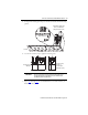
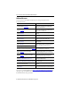
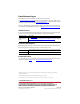
Motor Brake/Resistive Brake Connector
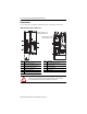
Power Wiring Requirements
Wire must be copper with 75 °C (167 °F) minimum rating. Phasing of main AC power is
arbitrary and earth ground connection is required for safe and proper operation.
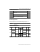
IAM Module Power Wiring Requirements
BC Pin Description Signal
6
Motor brake connections
MBRK-
5 MBRK+
4 Motor brake common COM
3 +24V brake input power (from LIM module or customer supplied) PWR
2
RBM module connections (from RBM module and safety string)
DBRK-
1 DBRK+
IMPORTANT
The National Electrical Code and local electrical codes take precedence over the values and
methods provided.
Module
IAM Module
Cat. No.
Description
Terminals Recommended
Wire Size
mm
2
(AWG)
Strip
Length
mm (in.)
Torque Value
N•m (lb•in)
Pin Signal
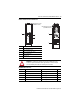
IAM
(460V)
2094-BC01-Mxx-
M
2094-BC02-M02-M
DC bus
(1)
and
VAC input power
(1) Keep DC common-bus connections (leader IAM to follower IAM module) as short as possible.
IPD-1
IPD-2
IPD-3
IPD-4
IPD-5
IPD-6
10…2.5
(8…14)
10
(0.38)
1.2…1.5
(10.6…13.2)
2094-BC04-M03-
M
10…6
(8…10)
16
(0.63)
2.4…3.0
(21.6…26.5)
2094-BC07-M05-
M 30 (3)
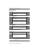
2094-BCxx-Mxx-
M
Control input
power
CPD-1 CTRL 2
4…2.5
(12…14)
10
(0.38)
0.5…0.6
(4.4…5.3)
CPD-2 CTRL 1
Contactor Enable
CED-1 CONT EN-
4…2.5
(12…14)
(2)
(2) The actual gauge of the contactor enable wiring depends on the system configuration. Consult your machine builder, the NEC, and applicable local
codes.
0.5…0.6
(4.4…5.3)
CED-2 CONT EN+
L3
L2
L1
DC-
DC+