
Installation Instructions Instruction Manual

12 Kinetix 6200 and Kinetix 6500 IAM and AM Power Modules
Rockwell Automation Publication 2094-IN011D-EN-P - August 2013
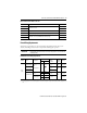
Connector Data
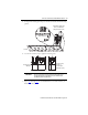
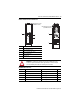
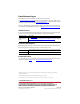
Use these illustrations to identify the IAM and AM power module features and indicators.
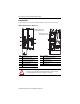
IAM Power Module Features and Indicators
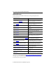
Item Description Item Description
1 Control power (CPD) connector 6 Motor/resistive brake (BC) connector
2 DC bus/AC input power (IPD) connector 7 Node address switch
3 Contactor Enable (CED) connector 8 Power-applied indicator
4 Motor cable shield clamp 9 Mounting screw
5 Motor power (MP) connector
ATTENTI ON: To avoid damage to equipment, do not mount your Bulletin 2094 control
module to the power module when the Power-applied indicator is on. Remove all input
power from the IAM power module before mounting the control module.
1 2
DC-
DC+
L3
L2
L1
CONT EN-
CONT EN+
CTRL 2
CTRL 1
1 2
1 2 3 4 5 6
W
V
U
MBRK -
MBRK +
COM
PWR
DBRK -
DBRK +
1 2 3 4
1 2 3 4 5 6
1
4
5
2
3
6
7
9
8
IAM Power Module, Top View
(2094-BC01-MP5-M is shown)
IAM Power Module, Front View
(2094-BC01-MP5-M is shown)