
User Manual Owner manual

Publication 2093-UM001A-EN-P — January 2007
90 Connecting the Kinetix 2000 Drive System
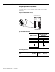
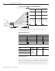
If the number of axes and other unique 24V power loads unique to certain
applications exceeds the capability of the LIM, the use of an external power
supply, such as those listed below, may be necessary.
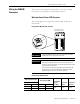
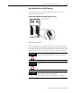
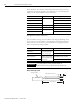
Wiring the Motor Brake Connections
The procedure for wiring your motor brake varies slightly, depending on the
motor series you are using. Refer to the table below to determine where the
brake wires for your servo motor are located and for the appropriate brake
cable or connector kit catalog number.
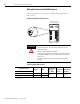
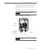
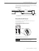
Brake Cable Preparation
Output Power Input Power Power Supply
30 W
85...264V ac 1606-XLP30E
50 W 1606-XLP50E
72 W 1606-XLP72E
80 W 85...267V ac 1606-XLS80E
100 W 85...264V ac 1606-XLP100E
120 W 85...267V ac 1606-XLS120E
240 W 1606-XLS240E
Motor Series Brake Wires Cable Catalog Number
MPL-A3xxx, MPL-A4xxx,
MPL-A45xxx
The motor has a brake
connector. Brake wires
are in the brake cable.
2090-UXNBMP-18Sxx brake cable
TL-Axxxx-H 2090-DANBT-18Sxx brake cable
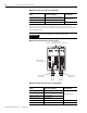
MPL-A15xxx, MPL-A2xxx,
MPF-A and MPS-A
The motor does not have
a brake connector. Brake
wires are included in the
power cable.
2090-XXNPMF-xxSxx power cable
Y-Series 2090-XXNPY-16Sxx power cable
IMPORTANT
Use surge suppression when controlling a brake coil.
Refer to the
Controlling a Brake Example on page 181.
BR+
BR-
105 mm (4.1 in.)
Outer Insulation
Strip Length 7 mm (0.28 in.)
Brake Cable