
User Manual Owner manual

Publication 2093-UM001A-EN-P — January 2007
74 Connecting the Kinetix 2000 Drive System
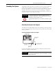
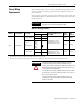
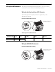
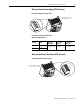
IAM/AM Power Wiring Requirements
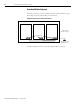
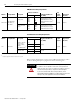
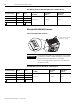
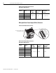
Shunt Module Power Wiring Requirements
Refer to Power Specifications on page 154 for additional information, and to
the Power Wiring Examples on page 169 for interconnect diagrams.
Module Catalog Number Description
Connects to Terminals
Recommended Wire Size
mm
2
(AWG)
Strip
Length
mm (in.)
Torque Value
Nm (lb-in.)
Pin Signal
IAM or AM
2093-AC05-MPx,
2093-AMPx, or
2093-AM0x
Motor power
MP-1
MP-2
MP-3
MP-4
Solid H05(07) V-U: 2.5(14)
Stranded H07 V-R: 2.5(14)
Flexible H05(07) V-K: 2.5(14)
Flexible with ferrule: 2.5(14)
(1)
6 (12) max
7 (0.28) 0.5 (4.4)
Brake control and
power
BC-1
BC-2
BC-3
BC-4
PWR
MBRK+
MBRK-
COM
Solid H05(07) V-U: 0.75(18)
Stranded H07 V-R: 0.75(18)
Flexible H05(07) V-K: 0.75(18)
Flexible with ferrule: 0.75(18)
1
)
The gauge of the motor power wiring is dependent on the drive and motor combination. Consult your machine builder, the NEC, and applicable local codes.
U
V
W
Module Catalog Number Description
Connects to Terminals
Recommended Wire Size
mm
2
(AWG)
Strip
Length
mm (in.)
Torque Value
Nm (lb-in.)
Pin Signal
SM 2093-ASP06
DC bus to external
passive shunt
module, catalog
number
1336-MOD-KA005
(1)
RC-1 DC+
10 (8)
(2)
7 (0.28) 0.5 (4.4)
RC-2 INT
RC-3 COL
Thermal switch
(1)
TS-1 TS1
0.75 (18)
TS-2 TS2
1
)
External shunt resistor is not supported in the initial release of Kinetix 2000 drive.
2
)
Requires copper wire rated for 105 °C (221 °F), 600V.
ATTENTION
This drive contains ESD (Electrostatic Discharge) sensitive parts and
assemblies. You are required to follow static control precautions
when you install, test, service, or repair this assembly. If you do not
follow ESD control procedures, components can be damaged.
If you are not familiar with static control procedures, refer to
Allen-Bradley publication 8000-4.5.2, Guarding Against Electrostatic
Damage or any other applicable ESD Protection Handbook.