
User Manual Owner manual

61 Publication 2093-UM001A-EN-P — January 2007
Chapter
5
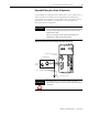
Connecting the Kinetix 2000 Drive System
Introduction
This chapter provides procedures for wiring your Kinetix 2000 system
components and making cable connections.
Basic Wiring Requirements
This section contains basic wiring information for the Kinetix 2000 drive.
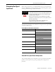
Topic Page
Basic Wiring Requirements 61
Determining Your Type of Input Power 63
Setting the Ground Jumper in Ungrounded Power Configurations 69
Grounding Your System 71
Power Wiring Requirements 73
Wiring Guidelines 76
Wiring the LIM Connectors 77
Wiring the IAM/AM Connectors 81
Feedback and I/O Cable Connections 92
Wiring 15-pin Panel-mounted Breakout Kit 97
Connecting Your SERCOS Fiber-optic Cables 99
ATTENTION
Plan the installation of your system so that you can perform all
cutting, drilling, tapping, and welding with the system removed from
the enclosure. Because the system is of the open type construction,
be careful to keep any metal debris from falling into it. Metal debris or
other foreign matter can become lodged in the circuitry, which can
result in damage to components.
SHOCK HAZAR
D
To avoid hazard of electrical shock, perform all mounting and wiring of
IAM, AM, SM, LIM, or power rail prior to applying power. Once power
is applied, connector terminals may have voltage present even when
not in use.
IMPORTANT
This section contains common PWM servo system wiring
configurations, size, and practices that can be used in a majority of
applications. National Electrical Code, local electrical codes, special
operating temperatures, duty cycles, or system configurations take
precedence over the values and methods provided.