
User Manual Owner manual

Publication 2093-UM001A-EN-P — March 2007
60 Kinetix 2000 Connector Data
Locating Shunt Module
Connectors and Indicators
The Kinetix 2000 shunt module (2093-ASP06) is suitable for both 230V
applications.
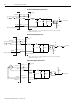
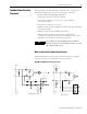
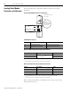
Locating Shunt Module Connectors and Indicators
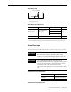
Shunt Module Connectors
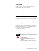
External Thermal Switch Two-pin (TS) Connector Pinout
External Shunt Resistor Three-pin (RC) Connector Pinout
Refer to Wiring 15-pin Panel-mounted Breakout Kit on page 97 when wiring
the RC and TS connectors.
321
21
DC+
INT
COL
TS1
TS2
Shunt Module, front view
(2093-ASP06)
Indicators:
Power Fault LED
Over-temp Fault LED
Bus Status LED
External Shunt Resistor
(RC) Connector
External Thermostat
(TS) Connector
Note External resistors not
supported at initial release.
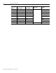
Designator Description Connector
TS Thermal switch connector Two-position connector housing
RC External shunt resistor connector Three-position connector housing
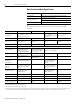
TS Pin Description Signal
1
External passive shunt module thermal
switch connections
(1), (2)
(1)
Factory default bypasses the external thermal switch by placing a jumper between TS-1 and TS-2.
(2)
External shunt resistor is not supported in the initial release of Kinetix 2000.
TS1
2 TS2
RC Pin Description Signal
1
External resistor connection
(1), (2)
(1)
Factory default bypasses the external shunt resistor by placing a jumper between RC-2 and RC-3.
(2)
External shunt resistor is not supported in the initial release of Kinetix 2000.
DC+
2 Internal shunt connection INT
3 Collector connection COL