
User Manual Owner manual

Publication 2093-UM001A-EN-P — March 2007
58 Kinetix 2000 Connector Data
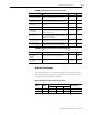
Motor Encoder Feedback Specifications
The following specifications apply to both motor and auxiliary feedback
channels.
Attribute Value
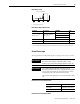
Encoder types Incremental, TTL, sine/cosine, Hiperface, and 17-bit serial
Max. input frequency
5.0 MHz (TTL input) per channel
250 kHz (sine/cosine input)
Commutation feedback Hall sensor
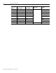
Specification 17-Bit Serial TTL Incremental Hiperface Sine/Cosine
Input voltage
Differential per EIA RS 422 5.0 V
U
H
_2.5 V at -I
H
= 20 mA
U
L
_2.5 V at -I
L
= 20 mA
0.8...1.2 V pk-pk
(1)
Protocol: 1V pk-pk Sine/Cos
with RS 485
0.6...1.2 V pk-pk
(2)
Input frequency — AM, BM, IM: 5 MHz max AM, BM: 250 kHz max
Line count 17-bit single-turn
Max limited by input signal
frequency
SRx: 1024 Sine/Cos per rev.
12-bit
Max limited by input signal
frequency
Interpolation — 4x line count 11-bit
Termination 120 Ω
Line loss detection
No response (all zeros) to
any position request, or
three consecutive bad
requests cause a CRC error.
Eight consecutive sample of
normalized absolute value of
A or B is < 0.75, and AQB
freq is < 10 kHz.
Avg (sin
2
+ cos
2
) > constant
Data communications RS 485 proprietary RS 422 RS 485, 9600 baud —
Support
Motor feedback channel
only
5V Incremental encoder with
differential AQB
— —
Memory support:
Programmed
Unprogrammed
Allen-Bradley motor data —
Allen-Bradley motor data
Encoders on auxiliary
channel
—
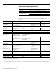
Multi-turn support
Power on
Power off
2
54
rotary, ±2
53
linear (revs)
4096 rotary, ±2047 linear
(revs)
—
2
54
rotary, ±2
53
linear (revs)
4096 rotary, ±2047 linear
(revs)
—
Single-turn support
Drive resolution equal to
unwind (modulo) value
without a battery.
—
Drive resolution equal to
unwind (modulo) value
without a battery.
—
Battery (2090-DA-BAT2)
External 3.6V, 50 mA max
(3)
— — —
Phase shift — — — 90º ±5º
Distance coded marker — — Not supported not supported
Hall inputs (S1, S2, S3) —
Single-ended, TTL or open
collector
—
Single-ended, TTL or open
collector
(1)
Voltages higher than 7V may cause product damage.
(2)
Voltages higher than 24V may cause product damage.
(3)
Battery to supply power for absolute encoder output from the TL-Series motors to the motor feedback connector on the drive must be installed in the Low Profile Connector
Kit for Motor Feedback, catalog number 2093-K2CK-D15M. Refer to publication 2093-IN005x-EN-P for information on wiring and installing this connector kit.