
User Manual Owner manual

Publication 2093-UM001A-EN-P — March 2007
50 Kinetix 2000 Connector Data
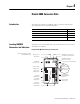
IAM and AM Motor Power and Brake Connector Pinouts
These connections have removable wiring plugs. The pins are numbered
consecutively from top to bottom, and keyed to prevent incorrect insertion.
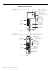
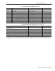
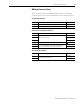
Motor Power Connector
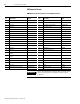
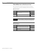
Motor Brake Connector
MP Pin Description Signal
1
Three-phase motor power
U
2V
3W
4 Chassis ground
IMPORTANT
To meet CE requirements, combined motor power cable length for all
axes on the same dc bus must not exceed 160 m (525 ft) with 230V
systems. Drive-to-motor power cables must not exceed 90 m (295.5
ft).
BC Pin Description Signal
1
+24V brake input power (from LIM or customer supplied)
PWR
2 MBRK+
3 Motor brake connections MBRK-
4 Motor brake common COM