
User Manual Owner manual

Publication 2093-UM001A-EN-P — March 2007
Kinetix 2000 Connector Data 47
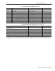
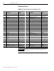
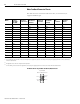
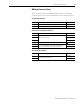
Auxiliary Feedback Device Pinouts
The table shows the connections made to the drive, or connector kit, for the
following common auxiliary feedback devices.
• Stegmann Hiperface (SKS, SKM, SRS, SRM)
• Sine/Cosine with Marker (0.6
...12V p-p)
• Differential TTL line driver (RS422) with marker
Pin Orientation for 44-pin I/O and Auxiliary Feedback (IOD/AF) Connector
IOD/AF Pin
(1)
Stegmann Hiperface
(2)
(SKS, SKM, SRS, SRM)
AQB Incremental Sine/Cosine Incremental
16 DATA- IM- IM-
17 DATA+ IM+ IM+
18
EPWR_5V
(3)
EPWR_5V
EPWR_5V
(3)
19 ECOM ECOM ECOM
20
EPWR_9V
(3)
–
EPWR_9V
(3)
31 BM- BM- BM-
32 BM+ BM+ BM+
33 AM- AM- AM-
34 AM+ AM+ AM+
(1)
The polarity of the feedback is defined as B leads A for positive sense.
(2)
Hiperface devices support only absolute homing.
(3)
Power depends on device requirement.
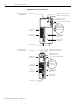
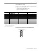
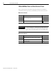
44-pin IAM/AM
I/O and Auxiliary Feedback Connector
Pin 30
Pin 44
Pin 1
Pin 15
Pin 16
Pin 31