
User Manual Owner manual

Publication 2093-UM001A-EN-P — March 2007
46 Kinetix 2000 Connector Data
I/O Connector Pinouts
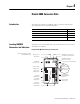
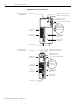
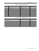
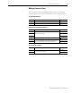
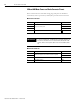
IAM/AM I/O and Auxiliary Feedback 44-pin (IOD/AF) Connector
IOD/AF
Pin
Description Signal
IOD/AF
Pin
Description Signal
1 Reserved — 23 Registration input 2 REG2
2 Reserved — 24 Registration input 2 24V 24V_REG2
3 Reserved — 25 Registration input 1 common 24VCOM_REG1
4 Reserved — 26 Registration input 1 REG1
5 Reserved — 27 Registration input 1 24V 24V_REG1
6 Reserved — 28 24V common 24VCOM
7 Reserved — 29 Overtravel input negative OT-
8 Reserved — 30 24V power output 24VPWR
9 Reserved — 31 Sine/A positive differential input SINE+/A+
10 Reserved — 32 Sine/A negative differential input SINE-/A-
11 Reserved — 33 Cosine/A positive differential input COSINE+/B+
12 Reserved — 34 Cosine/A negative differential input COSINE-/B-
13 Reserved — 35 Reserved —
14 Reserved — 36 24V common 24VCOM
15 Reserved — 37 Overtravel input positive OT+
16
Data/index positive differential input/
output
DATA+ / I+ 38 24V power output 24VPWR
17
Data/index negative differential input/
output
DATA- / I- 39 24V common 24VCOM
18 Encoder 5V power supply EPWR_5V 40 Home input HOME
19 Encoder common ECOM 41 24V power output 24VPWR
20 Encoder 9V power supply EPWR_9V 42 24V common 24VCOM
21 Reserved — 43 Enable ENABLE
22 Registration input 2 common 24VCOM_REG2 44 24V power output 24VPWR
IMPORTANT
Signals +24V_PWR and +24V_COM are a 24V dc source that should
only be used to power inputs on the 44-pin I/O and AF connector
listed above.