
User Manual Owner manual

Publication 2093-UM001A-EN-P — March 2007
Kinetix 2000 Connector Data 45
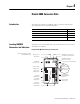
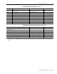
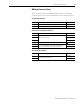
Integrated Axis Module/Axis Module Connectors
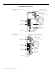
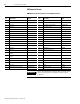
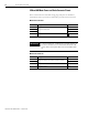
Integrated Axis Module/Axis Module Switches and Indicators
Designator Description Connector Present on IAM or AM
BC Motor brake 4-position plug/header IAM/AM
CED Contactor enable 2-position plug/header IAM
CPD Control input power (drive) 2-position plug/header IAM
DPI Drive peripheral interface (factory use only) 8-pin mini-DIN IAM
IOD/AF User I/O (drive) and auxiliary feedback 44-pin high-density D-shell (female) IAM/AM
IPD V ac input power (drive) 230V and dc bus 6-position plug/header IAM
MF Motor feedback 15-pin high-density D-shell (female) IAM/AM
MP Motor power 4-position plug/header IAM/AM
Tx and Rx SERCOS transmit and receive SERCOS fiber-optic (2) IAM/AM
Description Type Present on IAM or AM
SERCOS Node Address
(1)
Rotary switches IAM
SERCOS Baud Rate and Optical Power DIP switches IAM and AM
Fault or SERCOS Status Seven segment LED indicator IAM and AM
Drive Status LED indicator IAM and AM
Communication Status LED indicator IAM and AM
Bus Power Status LED indicator IAM and AM
(1)
The node address setting for the IAM establishes the base address (n) for that power rail, and the address for the other axis modules (AMs) increment from the base
address (2093-AMPx = n + 1, and 2093-AM0x = n + 2). Refer to the Node Addressing Example 4 on page 108 for information on physical and logical addressing of axis
modules.