
User Manual Owner manual

43 Publication 2093-UM001A-EN-P — March 2007
Chapter
4
Kinetix 2000 Connector Data
Introduction
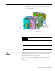
This chapter provides power, feedback, and I/O connector locations and
signal descriptions for your Kinetix 2000 drive.
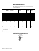
Locating IAM/AM
Connectors and Indicators
The physical size of the modules may vary, but the location of the connectors
and indicators is identical.
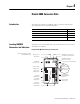
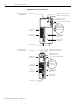
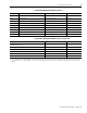
Integrated Axis Module Connectors and Indicators
Topic Page
Locating IAM/AM Connectors and Indicators 43
IAM/AM Signal Specifications Explained 51
Feedback Specifications Explained 57
Locating Shunt Module Connectors and Indicators 60
Indicators:
Drive Status LED
COMM Status LED
Bus Status LED
SERCOS Transmit (Tx) Connector
SERCOS Receive (Rx) Connector
SERCOS Baud Rate and
Optical Power Switches
Seven Segment Fault Status Displa
y
I/O and Machine
Feedback (IOD/AF)
Connector
Motor Feedback
(MF) Connector
Motor Power
(MP) Connector
Motor Brake
(BC) Connector
Contactor Enable
(CED) Connector
Control Power
(CPD) Connector
Main Power
(IPD) Connector
DPI Connector
SERCOS Node
Address Switches
Mounting Screw
Mounting Tabs
Integrated Axis Module, Front View
(2093-AC05-MPx shown)