
User Manual Owner manual

37 Publication 2093-UM001A-EN-P — March 2007
Chapter
3
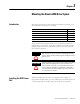
Mounting the Kinetix 2000 Drive System
Introduction
This chapter provides the system installation procedures for mounting your
Kinetix 2000 drive components to the panel.
The procedures in this chapter assume you have prepared your panel and
understand how to bond your system. For installation instructions regarding
equipment and accessories not included here, refer to the instructions that
came with those products.
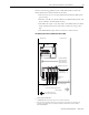
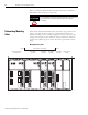
Installing the 2093 Power
Rail
The Kinetix 2000 power rail comes in configurations that support one
integrated axis module (IAM), up to seven additional axis modules (AM), and
a shunt module (SM). A slot filler (SF) must occupy any open position.
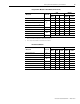
Topic Page
Installing the 2093 Power Rail 37
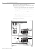
Determining Mounting Order 38
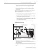
Mount the Modules 40
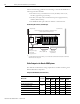
Mounting the Line Interface Module 41
Segregating Power and Logic Wires 42
WARNING
To avoid hazard of electrical shock, perform all mounting and wiring of
IAM, AM, SM, SF, LIM, or power rail prior to applying power. Once
power is applied, connector terminals may have voltage present even
when not in use.
ATTENTION
Plan the installation of your system so that you can perform all cutting,
drilling, tapping, and welding with the system removed from the
enclosure. Because the system is of the open type construction, be
careful to keep any metal debris from falling into it. Metal debris or
other foreign matter can become lodged in the circuitry, which can
result in damage to components.