
User Manual Owner manual

Publication 2093-UM001A-EN-P — March 2007
Planning the Kinetix 2000 Drive System Installation 35
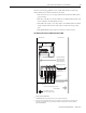
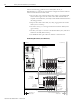
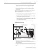
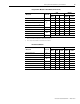
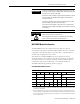
Integrated Axis Module or Axis Module (Inverter Side)
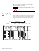
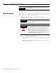
Line Interface Module
Wire/Cable Connector
Zone Method
Very
Dirty
Dirty Clean
Ferrite
Sleeve
Shielded
Cable
U, V, W (motor power) MP X X
MBRK-, MBRK+ (motor brake)
BC
X
COM, PWR (24V dc), filtered
(1)
X
COM, PWR (24V dc), unfiltered
(2)
X
Motor feedback MF X X
Auxiliary feedback AF X X
Registration outputs
IOD
XX
Others X
Fiber-optic Rx and Tx No Restrictions
(1)
This is a clean 24V dc available for any device that may require it.
(2)
This is a dirty 24V dc available for motor brakes and contactors.
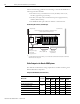
Wire/Cable Connector
Zone Method
Very
Dirty
Dirty Clean
Ferrite
Sleeve
Shielded
Cable
V ac line (main input) IPL X
230V ac input APL X
V ac load (shielded option)
OPL
XX
V ac load (unshielded option) X
Control power output CPL X
MBRK PWR, MBRK COM P1L/PSL X
Status I/O IOL X
Auxiliary 230V ac P2L X