
User Manual Owner manual


Publication 2093-UM001A-EN-P — March 2007
24 Planning the Kinetix 2000 Drive System Installation
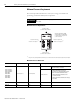
Minimum Clearance Requirements
This section provides information to assist you in sizing your cabinet and
positioning your Kinetix 2000 system components.
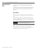
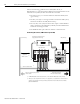
Minimum Clearance Requirements
(1)
The power rail, catalog number 2093-PRSxx, does not extend left of the first module or right of the last module.
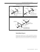
Minimum Clearance Dimensions
IMPORTANT
Mount the module in an upright position. Do not mount the module on
its side.
Clearance right of the
module is not required.
(1)
Clearance above
for airflow and installation.
Clearance left of the
module is not required.
(1)
Integrated Axis Module (IAM),
catalog number 2093-AC05-MP1,
is shown mounted on power rail
as the first module.
Clearance below
for airflow and installation.
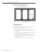
Cat. No. Clearance Above, Min Clearance Below, Min
Cabinet Depth Clearance, Min
(1)
2093-AC05-MP1,
2093-AC05-MP2,
2093-AC05-MP5.
2093-AMP1,
2093-AMP2,
2093-AMP5,
2093-AM01,
2093-AM02
50.8 mm (2.0 in.) 50.8 mm (2.0 in.)
200 mm (7.9 in.)
If 15-pin connector kit, catalog number
2090-K2CK-D15M, is attached.
235 mm (9.25 in.)
44-pin connector kit options include:
• 2090-U3BK-D44xx connector kit
(containing a 2090-U3BK-D44 terminal
block and 2090-U3BK-D44xx cable)
• 2090-U3BK-D44 terminal block and
custom-built cable.
• 2090-U3BK-D44 terminal block and flying
lead cable.
2093-ASP06 305 mm (12.0 in.) 50.8 mm (2.0 in.) 200 mm (7.9 in.)
2093-PRF None None None
(1)
Additional clearance required to accommodate cable bend restrictions.