
User Manual Owner manual


Publication 2093-UM001A-EN-P — March 2007
22 Planning the Kinetix 2000 Drive System Installation
dissipation data from other equipment inside the enclosure (such as
ControlLogix controller). Once the total amount of heat dissipation (in Watts)
is known, the minimum enclosure size can be calculated.
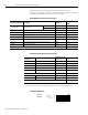
Kinetix 2000 System Heat Dissipation Example
ControlLogix System Heat Dissipation Example
ControlLogix Real Power
Enclosure Component Description
Loading
(1)
Heat Dissipation
(1)
Watts
2093-AC09-M02
Integrated axis module (IAM),
230V, three-phase
3 kW (converter section) 20% 7.0
1 A (inverter section) 40% 33.6
2093-AM02 Axis module (AM), 230V, 9 A 60% 67.3
2093-AM02 Axis module (AM), 230V, 9 A 60% 67.3
2093-AM01 Axis module (AM),230V, 6 A 40% 46.7
2093-AM01 Axis module (AM), 230V, 6 A 40% 46.7
2093-AM01 Axis module (AM), 230V, 6 A 20% 46.7
2093-AL09 Line interface module (LIM), 230V, 6 kW, 6 A; 24V dc 3 A 100% 72.0
2093-PR6 Power rail, 230V, 6 axis N/A 0.0
Total Kinetix 2000 system Wattage
387.3
(1)
To determine heat dissipation specifications for the Kinetix 2000 components, refer to Power Dissipation Specifications on page 160.
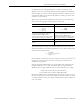
Enclosure
Component
Description
Backplane Power
Load
(1)
Watts
Heat Dissipation
(1)
Watts
1756-M08SE 8-axis SERCOS interface module 3.2 0
1756-L55M12 5555 ControlLogix processor 4.5 0
1756-IB16D 16 -point input module 0.84 5.8
1756-OB16D 16 -point output module 4.64 3.3
1756-ENBT Ethernet communications module 4.0 0
Backplane total
17.18
(2)
N/A
1756-PB72 24V dc ControlLogix power supply N/A
25
(2)
1756-A7 7-slot mounting chassis N/A N/A
Total ControlLogix system Wattage 34.1
(1)
For ControlLogix module specifications, refer to the ControlLogix Selection Guide, publication 1756-SG001.
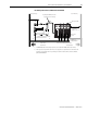
(2)
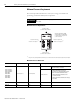
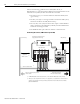
Real power heat dissipation is determined by applying the backplane power load (17.18 W) to the graph below.
75
60
45
30
15
0
0 20 40 60 80 100
Backplane dc
Power Load
(Watts)
Real Power (Watts)
1756-P B72
1756-P B75