
User Manual Owner manual

Publication 2093-UM001A-EN-P — March 2007
Interconnect Diagrams 185
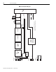
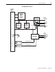
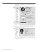
Shunt Module Block Diagram
AUX+
AUX-
DC+
CHASSIS
GROUND
DC-
SYS_OK_IN
SYS_OK_OUT
GSHUNT+
GSHUNT-
DC+
INT
COL
TS1
TS2
POWER
RAIL
SHUNT
TEMP
BUS
LED
Indicators
Signal
Connection
Shunt Command
Shunt
Resistor
Switch
Mode
Power
Supply
System OK Command
DC Bus
Capacitor
Controller
External
Connectors
Bus Voltage
System OK
Receiver
Bus
Voltage
Detector