
User Manual Owner manual

Publication 2093-UM001A-EN-P — March 2007
Interconnect Diagrams 183
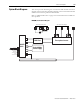
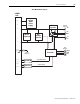
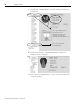
System Block Diagrams
This section provides block diagrams of the Kinetix 2000 modules. For block
diagrams of the line interface module (LIM) refer to the Line Interface Module
Installation Instructions, publication 2094-IN005.
Refer to Additional Resources on page 10 for the documentation available for
those products.
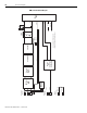
IAM/AM (inverter) Block Diagram
POWER
RAIL
DC+
WV
U
AUX+
AUX-
SYSOK
CONV_ID (5)
GSHUNT (2)
CAN (2)
MBRK
Switch Mode
Power Supply
PWR
DC-
EMI Filter
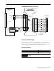
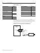
Three-phase Motor OutputMotor Brake Connections
Three-phase Inverter
Chassis