Installation Instructions Kinetix 2000 Integrated Axis Module and Axis Module Catalog Numbers 2093-AC05-MP1, 2093-AC05-MP2, 2093-AC05-MP5, 2093-AMP1, 2093-AMP2, 2093-AMP5, 2093-AM01, 2093-AM02 Topic Page Important User Information 2 Before You Begin 3 Installing a Kinetix 2000 Drive 3 IAM and AM Connector Data 7 Wiring Requirements 12 Motor Overload Protection 14 Additional Resources 15 About the Kinetix 2000 Drives The Kinetix® 2000 integrated axis module (IAM) and up to seven axis modules
Kinetix 2000 Multi-axis Servo Drives Important User Information Read this document and the documents listed in the additional resources section about installation, configuration, and operation of this equipment before you install, configure, operate, or maintain this product. Users are required to familiarize themselves with installation and wiring instructions in addition to requirements of all applicable codes, laws, and standards.
Kinetix 2000 Multi-axis Servo Drives 3 Before You Begin Remove all packing material, wedges, and braces from within and around the components. After unpacking, check the catalog number on the name-plate against the purchase order.
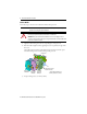
Kinetix 2000 Multi-axis Servo Drives Set the IAM Ground Jumper for the Power Grounding Configuration Setting the ground jumper is necessary only when using an ungrounded or high-impedance grounded power configuration. Refer to the Kinetix 2000 Multi-axis Servo Drives User Manual, publication 2093-UM001, for diagrams illustrating grounded and ungrounded input power. Follow these steps to set the ground jumper for ungrounded or high-impedance grounded power configurations. 1.
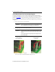
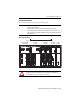
Kinetix 2000 Multi-axis Servo Drives 5 Determine Mounting Order Mount axis modules in the order (left to right) shown in the figure. IMPORTANT The integrated axis module (IAM) must be positioned in the leftmost slot on the power rail, followed by axis modules (AM). Mount axis modules from left to right starting with the highest power utilization. The shunt module is mounted to the right of the last AM module.
Kinetix 2000 Multi-axis Servo Drives Mount a Module Follow these steps to mount an axis module on the Kinetix 2000 power rail. IMPORTANT The IAM module must be positioned in the leftmost slot of the power rail, followed by AM modules in descending order of power utilization. ATTENTION: To avoid damage to pins on the back of each module, and to make sure that module pins mate properly with the power rail, install modules as shown below.
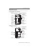
Kinetix 2000 Multi-axis Servo Drives 7 IAM and AM Connector Data Use these illustrations to identify the IAM and AM module connectors and indicators.
Kinetix 2000 Multi-axis Servo Drives Connector Descriptions Designator Description Connector BC Motor brake 4-position plug/header Contactor enable 2-position plug/header Control input power (drive) 2-position plug/header Drive peripheral interface (factory use only) 8-pin mini-DIN User I/O (drive) and auxiliary feedback 44-pin high-density D-shell (female) CED (1) CPD (1) DPI (1) IOD/AF (1) 230V AC input power (drive) and DC bus 6-position plug/header MF Motor feedback 15-pin high
Kinetix 2000 Multi-axis Servo Drives 9 Main Power and DC Bus (IPD) Connector IPD Pin Description Signal 1 L1 2 Single- or three-phase input power (230V AC) 4 Chassis ground 5 An integral, unregulated power supply, consisting of AC line, three-phase bridge rectifier, and filter capacitors 6 (1) L2 L3 (1) 3 DC+ DC- Not used with single-phase power. Motor Power and Brake Connector Pinouts These connectors are supplied with removable wiring plugs and are keyed to prevent incorrect insertion.
Kinetix 2000 Multi-axis Servo Drives I/O Connector Pinouts These connections require customer-supplied connectors.
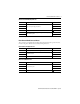
Kinetix 2000 Multi-axis Servo Drives 11 IAM and AM Motor Feedback 15-pin (MF) Connector MF Pin Stegmann Hiperface Tamagawa 17-bit Serial (1) Sine/ Cosin (2) Sine/ Cosine (3) AQB (2) AQB (3) Renishaw 1 AM+ – AM+ AM+ AM+ AM+ AM+ 2 AM- – AM- AM- AM- AM- AM- 3 BM+ – BM+ BM+ BM+ BM+ BM+ 4 BM- – BM- BM- BM- BM- BM- 5 DATA+ DATA+ IM+ IM+ IM+ IM+ IM+ 6 ECOM ECOM ECOM ECOM ECOM ECOM ECOM 7 (4) – – – – – – – 8 – – S3 – S3 – S3 9 – – – – –
Kinetix 2000 Multi-axis Servo Drives Wiring Requirements Wire must be copper with 75 °C (167 °F) minimum rating. Phasing of main AC power is arbitrary, and an earth ground connection is required for safe and proper operation. ATTENTION: To avoid personal injury and/or equipment damage, make sure installation complies with specifications regarding wire types, conductor sizes, branch circuit protection, and disconnect devices.
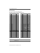
Kinetix 2000 Multi-axis Servo Drives 13 IAM and AM Module Power Wiring Requirements Connects to Terminals Pin Signal Recommended Wire and Size mm2 (AWG) Strip Length mm (in.) Torque Value N•m (lb•in) Brake BC-1 BC-2 BC-3 BC-4 PWR BRK+ BRKCOM Solid H05(07) V-U: 0.75 (18) Stranded H07 V-R: 0.75 (18) Flexible H05(07) V-K: 0.75 (18) Flexible with ferrule 0.75 (18) 7.0 (0.28) 0.5 (4.4) Motor MP-1 MP-2 MP-3 MP-4 U V W Motor power cable depends on motor/drive combination 2.5 (14) 7.0 (0.28) 0.
Kinetix 2000 Multi-axis Servo Drives Motor Overload Protection This servo drive uses solid-state motor overload protection that operates in accordance with UL 508C. Motor overload protection is provided by algorithms (thermal memory) that predict actual motor temperature based on operating conditions as long as control power is continuously applied. However, when control power is removed, thermal memory is not retained.
Kinetix 2000 Multi-axis Servo Drives 15 Additional Resources These documents contain additional information concerning related products from Rockwell Automation. Resource Description Kinetix 2000 Multi-axis Servo Drives User Manual, publication 2093-UM001 Provides information on how to install, configure, startup, and troubleshoot your Kinetix 2000 servo drive system.
Rockwell Automation Support Rockwell Automation provides technical information on the Web to assist you in using its products. At http://www.rockwellautomation.com/support you can find technical and application notes, sample code, and links to software service packs. You can also visit our Support Center at https://rockwellautomation.custhelp.com/ for software updates, support chats and forums, technical information, FAQs, and to sign up for product notification updates.