
Design Guide User guide
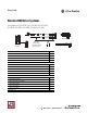
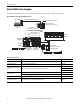
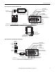
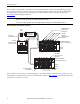
Table Of Contents
- Front Cover - Kinetix 2000 Drive Systems Design Guide
- Introduction
- Determine What You Need
- Kinetix 2000 System Examples
- 2090-Series Motor/Actuator Cables Overview
- Kinetix 2000 Drives with MPL
- Kinetix 2000 Drives with MPM
- Kinetix 2000 Drives with MPF
- Kinetix 2000 Drives with MPS
- Kinetix 2000 Drives with TLY
- Bulletin TLY Motor Cable Combinations
- Bulletin TLY (non-brake) Motor Performance Specifications with Kinetix 2000 Drives
- Bulletin TLY (brake) Motor Performance Specifications with Kinetix 2000 Drives
- Kinetix 2000 Drives/TLY-AxxxP-B (absolute high-resolution) Motor Curves
- Kinetix 2000 Drives/TLY-AxxxT-H (incremental) Motor Curves
- Kinetix 2000 Drives/TLY-Axxxx-x Motor Curves
- Kinetix 2000 Drives with MPAS
- Kinetix 2000 Drives with MPAR
- Kinetix 2000 Drives with MPAI
- Kinetix 2000 Drives with TLAR
- Kinetix 2000 Drives with LDC-Series
- Kinetix 2000 Drives with LDL-Series
- Additional Resources
- Back Cover
6 Rockwell Automation Publication GMC-RM006A-EN-P - September 2011
Kinetix 2000 Drive Systems
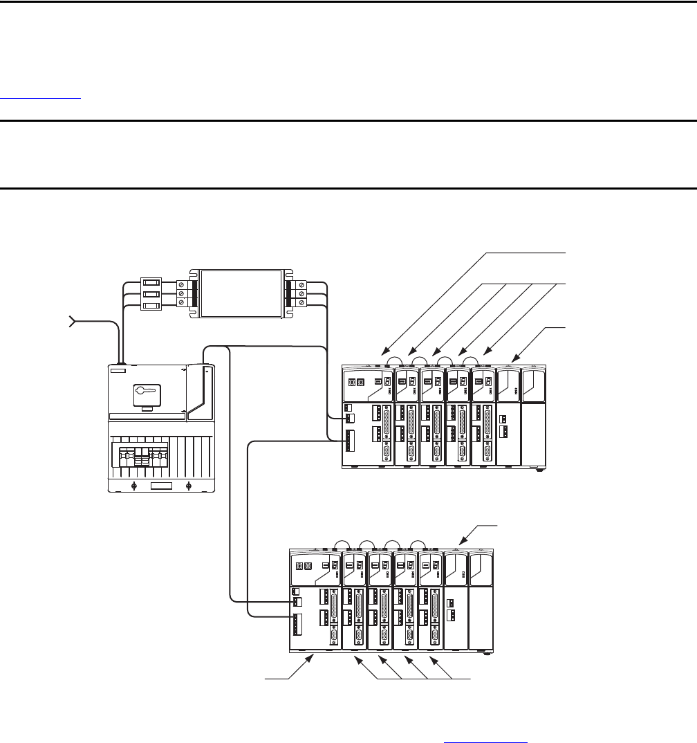
In this example, the leader IAM is connected to the follower IAM via the DC common bus. When planning your panel
layout, you must calculate the total bus capacitance of your DC common bus system to make sure that the leader IAM is
sized sufficiently to pre-charge the entire system. Refer to the Kinetix 2000 Servo Drive User Manual, publication
2093-UM001
, when making this calculation.
Kinetix 2000 Input Power Example (DC common bus)
Motor-end cable connector kits, for use when building your own cables, and panel-mounted breakout components are also
available. Refer to the Kinetix Motion Accessories Technical Data, publication GMC-TD004
, for detailed descriptions and
specifications of servo drive accessories.
IMPORTANT
If total bus capacitance of your system exceeds the leader IAM pre-charge rating, the IAM seven-segment status indicator will
display error code E90 (pre-charge timeout fault) if input power is applied.
To correct this condition, you must remove axis modules from the power rail to decrease the total bus capacitance.
MAIN VAC
Three-phase
Input Power
2094-ALxxS
Line Interface Module
(optional component)
Axis Modules (4)
2093-AMxx
Integrated Axis Module
2093-AC05-MPx
Shunt Module
(optional component)
2093-ASP06
2093-PRF Slot-filler Module
(required to fill any unused slots)
Power Rail
2093-PRSx
Axis Modules (4)
2093-AMxx
Integrated Axis Module
2093-AC05-MPx
Shunt Module
(optional component)
2093-ASP06
Power Rail
2093-PRSx
230V Control Power
DC Common Bus
AC Line Filter
2090-XXLF-TCxxx
(required for CE)
Input
Fusing
2093-PRF Slot-filler Module
(required to fill any unused slots)