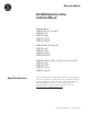
Ultra3000 Digital Servo Drives (Catalog Numbers 2098-DSD-005, -010, and -020 2098-DSD-xxxX 2098-DSD-xxx-SE 2098-DSD-xxx-DN 2098-DSD-xxxX-DN 2098-DSD-030, -075, and -150 2098-DSD-xxxX 2098-DSD-xxx-SE 2098-DSD-xxx-DN 2098-DSD-xxxX-DN 2098-DSD-HV030, -HV050, -HV100, -HV150, and -HV220 2098-DSD-HVxxxX 2098-DSD-HVxxx-SE 2098-DSD-HVxxx-DN 2098-DSD-HVxxxX-DN) Installation Manual
Important User Information Because of the variety of uses for the products described in this publication, those responsible for the application and use of this control equipment must satisfy themselves that all necessary steps have been taken to assure that each application and use meets all performance and safety requirements, including any applicable laws, regulations, codes and standards.
Summary of Changes The Ultra3000 Digital Servo Drive Installation Manual Document Update, publication 2098-DU003B-EN-P, includes important information about changes and updates to this Ultra3000 Digital Servo Drive Installation Manual. The document update used to be provided as a separate document, but is now incorporated into this installation manual, in the section immediately following this Summary of Changes section, and before the Table of Contents.
Summary of Changes Notes: II Rockwell Automation Publication 2098-IN003E-EN-P - March 2012
Document Update Ultra3000 Digital Servo Drive Installation Manual Catalog Numbers 2098-DSD-005, -010, and -020 2098-DSD-xxxX 2098-DSD-xxxSE 2098-DSD-xxx-DN 2098-DSD-xxxX-DN 2098-DSD-030, -075, and -150 2098-DSD-xxxX 2098-DSD-xxxSE 2098-DSD-xxx-DN 2098-DSD-xxxX-DN 2098-DSD-HV030, -HV050, -HV100, -HV150, and -HV220 2098-DSD-xxxX 2098-DSD-xxxSE 2098-DSD-xxx-DN 2098-DSD-xxxX-DN About This Publication This document updates information about the Ultra3000 digital servo drive products.
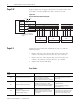
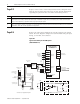
2 Ultra3000 Digital Servo Drive Installation Manual Page 2-52 Replace Figure 2.57 on page 2-52 with the one shown below. The new figure correctly identifies the drive connector as CN3. Figure 2.57 RS-232 to RS-485 Connection Diagram +12V dc RS-232 Interface COM PC RCV XMT Common 232 to 485 Adapter 7 3 2 COM 7 RCV- 5 RCV+ 17 XMT- 3 XMT+ 14 Note: Pin-outs vary by manufacturer. This example uses a B&B 485 adapter.
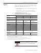
Ultra3000 Digital Servo Drive Installation Manual Page A-2 3 Replace the Ultra3000 (230V) Power Specifications table on page A-2 with the one shown below. The new table includes inrush current specifications configured as Series A, B, or C. • Ultra3000 drive firmware revision 1.45 is required to support the Series C hardware. • Ultraware software, version 1.63, is required to download firmware to Series C drives containing the new power board.
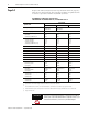
4 Ultra3000 Digital Servo Drive Installation Manual Page A-3 Replace the Ultra3000 (230V) Power Specifications table on page A-3 with the one shown below. The new table includes an updated value in the bus capacitance field for 2098-DSD-030 drives. Ultra3000 Drive (230V) Power Specifications 2098-DSD-030x-xx, 2098-DSD-075x-xx, and 2098-DSD-150x-xx Description Specification 2098-DSD-030 2098-DSD-075 AC input voltage (1) 100...240V rms Single-phase 100...240V rms Three-phase AC input frequency 47..
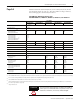
Ultra3000 Digital Servo Drive Installation Manual Page A-4 5 Add the attention statement (below) to the Ultra3000 (460V) Power Specifications table on page A-4. The table didn’t change, however, the warning applies to all Ultra3000 drives. Ultra3000 Drive (460V) Power Specifications 2098-DSD-HV030x-xx, -HV050x-xx, -HV100x-xx, -HV150x-xx, and -HV220x-xx Description Specification 2098-DSD-HV030 2098-DSD-HV050 2098-DSD-HV100 2098-DSD-HV150 2098-DSD-HV220 7A 6A 14 A 6A 20 A 6A 28 A 6A 230...
6 Ultra3000 Digital Servo Drive Installation Manual Page B-2 Replace notes 6 and 7 in the Ultra3000 Interconnect Diagram Notes with the ones shown below. The new versions include information regarding the placement of ac line filters and routing of wires. Note: Information: 6 May be used to maintain power to logic section of drive and status LED indicators when main ac input power is removed.
Ultra3000 Digital Servo Drive Installation Manual Page B-5 7 Replace the interconnect diagram on page B-5 with the one shown below. The new diagram changes the recommended wiring of input fusing, ac line filter, and contactor. Figure B.
8 Ultra3000 Digital Servo Drive Installation Manual Page B-6 Replace the interconnect diagram on page B-6 with the one shown below. The new diagram changes the recommended wiring of input fusing, ac line filter, and contactor. Figure B.
Ultra3000 Digital Servo Drive Installation Manual Page B-12 9 Replace Figure B.12 on page B-12 with the one shown below. The new figure includes MP-Series food grade (MPF), stainless steel (MPS) and low inertia (MPL-A/B15xx and MPL-A/B2xx) motors. Also included is an illustration of grounding the feedback cable shield. Figure B.
10 Ultra3000 Digital Servo Drive Installation Manual Page B-13 Replace Figure B.13 on page B-13 with the one shown below. The new figure correctly identifies the motor brake-connector pins as A and B. Also included is an illustration of grounding the feedback cable shield. Figure B.
Ultra3000 Digital Servo Drive Installation Manual Page B-15 11 Replace Figure B.15 on page B-15 with the one shown below. The new figure correctly identifies the motor power-cable pins as 1, 2, 3, and 5. Also included is an illustration of grounding the feedback cable shield. Figure B.
Page B-19 Replace the table on page B-19 with the one shown below. The new table includes the MPL-x15xx, MPL-x2xx, and TL-Series motors. Compatible Brake Motors Coil Current Compatible Brake Motors Coil Current MPL-x15xx (1) 0.48 A 1326AB-B4xxx 0.88 A MPL-x2xx (1) 0.51 A F-4030, -4050, and -4075 0.69 A MPL/MPF/MPS-x310, -x320, -x330 (1) 0.50 A Y-1002 and -1003 0.26 A Y-2006 and -2012 0.31 A Y-3023 0.37 A TL-A110P-H, -A120P-H, and -A130P-H 0.208 A TL-A220P-H and -A230P-H 0.
Table of Contents Preface Introduction . . . . . . . . . . . . . . . . . . . . . . . . . Who Should Use this Manual . . . . . . . . . . . . . Purpose of this Manual . . . . . . . . . . . . . . . . . Contents of this Manual . . . . . . . . . . . . . . . . . Product Receiving and Storage Responsibility . Related Documentation . . . . . . . . . . . . . . . . . Conventions Used in this Manual . . . . . . . . . . Allen-Bradley Support . . . . . . . . . . . . . . . . . . Local Product Support . . . . . . . . . .
ii Table of Contents Analog ILIMIT Input . . . . . . . . . . . . . . . . . . . . . . . . . . Analog Output . . . . . . . . . . . . . . . . . . . . . . . . . . . . . . Understanding Motor Encoder Feedback Specifications . . . AM, BM, and IM Inputs . . . . . . . . . . . . . . . . . . . . . . . . Hall Inputs . . . . . . . . . . . . . . . . . . . . . . . . . . . . . . . . . Thermostat Input . . . . . . . . . . . . . . . . . . . . . . . . . . . . + Limit and - Limit Inputs . . . . . . . . . . . . . . . . . . .
Table of Contents iii Chapter 4 Troubleshooting Status Indicators Chapter Objectives. . . . . . . . . . . . . . . . . . . . . . . . . . . . . . . 4-1 Safety Precautions . . . . . . . . . . . . . . . General Troubleshooting . . . . . . . . . . Error Codes . . . . . . . . . . . . . . . . . Troubleshooting for SERCOS Drives . . SERCOS Module Status LED . . . . . SERCOS Network Status LED. . . . . Troubleshooting for DeviceNet Drives DeviceNet Module Status LED . . . . DeviceNet Network Status LED . . . . .
iv Table of Contents Controlling a Brake Example . . . . . . . . . . . . . . . . . . . . . . B-19 Ultra3000 to Logix Cable and Interconnect Diagrams . . . . . B-20 Ultra3000 to IMC-S Compact Cable and Interconnect Diagram . . . . . . . . . . . . . . . . . . . . . . B-23 Appendix C Catalog Numbers and Accessories Chapter Objectives . . . . . . . . . . . . . . . . . . . . . . . . . . . . . . . C-1 Ultra3000 Drives . . . . . . . . . . . . . . . . . . Software . . . . . . . . . . . . . . . . . . . . . . . .
Preface Introduction Who Should Use this Manual Read this preface to familiarize yourself with the rest of the manual. This preface contains the following topics: • Who Should Use this Manual • Purpose of this Manual • Contents of this Manual • Product Receiving and Storage Responsibility • Related Documentation • Conventions Used in this Manual • Allen-Bradley Support Use this manual for designing, installing, and wiring your Ultra™3000 Digital Servo Drive (DSD).
P-2 Preface Contents of this Manual Refer to the following listing for the descriptive contents of this installation manual. Chapter Product Receiving and Storage Responsibility Title Contents Preface Describes the purpose, background, and scope of this manual. Also specifies the audience for whom this manual is intended. 1 Installing Your Ultra3000 Provides mounting information for the Ultra3000.
Preface Related Documentation P-3 The following documents contain additional information concerning related Allen-Bradley products. To obtain a copy, contact your local Allen-Bradley office, distributor, or download them from www.theautomationbookstore.
P-4 Preface Conventions Used in this Manual Allen-Bradley Support The following conventions are used throughout this manual.
Chapter 1 Installing Your Ultra3000 Chapter Objectives This chapter provides system installation guidelines and procedures for mounting your Ultra3000. This chapter covers the following topics: • Complying with European Union Directives • Ultra3000 System Component Overview • Before Mounting Your System • HF Bonding Your System • Planning Your Panel Layout • Mounting Your Ultra3000 Drive ATTENTION ! 1 The following information is a guideline for proper installation.
1-2 Installing Your Ultra3000 Complying with European Union Directives If this product is installed within the European Union or EEC regions and has the CE mark, the following regulations apply. Note: Declarations of Conformity (DOCs) to European Union Directives are available on-line at www.ab.com/certification/ce/ docs. The web site is the authoritative source for verifying compliance and suitability for use of this and other Rockwell Automation/Allen-Bradley products.
Installing Your Ultra3000 1-3 Low Voltage Directive These units are tested to meet Council Directive 73/23/EEC Low Voltage Directive. The EN 60204-1 Safety of Machinery-Electrical Equipment of Machines, Part 1-Specification for General Requirements standard applies in whole or in part. Additionally, the standard EN 50178 Electronic Equipment for use in Power Installations applies in whole or in part. Refer to Appendix B for interconnect information.
1-4 Installing Your Ultra3000 The typical Ultra3000 system installation includes the following, as shown in the figures below. Figure 1.
Installing Your Ultra3000 1-5 Figure 1.
1-6 Installing Your Ultra3000 System Mounting Requirements There are several things that you need to take into account when preparing to mount the Ultra3000: • The Ultra3000 must be enclosed in a grounded conductive enclosure offering protection as defined in standard EN 60529 (IEC 529) to IP22 such that they are not accessible to an operator or unskilled person, in order to comply with UL® and CE requirements. A NEMA 4X enclosure exceeds these requirements providing protection to IP66.
Installing Your Ultra3000 1-7 Ventilation Requirements This section provides information to assist you in sizing your cabinet and locating your Ultra3000 drive(s) inside the cabinet. Figure 1.4 Minimum Clearance Requirements 50.8 mm (2.0 in.) clearance for airflow and installation Ultra3000 mounted vertically on the panel Do not mount drive on its side. Allow 12.7 mm (0.5 in.) side clearance Allow 12.7 mm (0.5 in.) side clearance Minimum cabinet depth = 243.8 mm (9.6 in.) Minimum front clearance = 76.
1-8 Installing Your Ultra3000 Sizing an Enclosure As an additional aid in sizing an enclosure, with no active method of heat dissipation, either of the following approximate equations can be used: Metric Standard English 0.38Q A = ----------------------1.8T – 1.1 4.08Q A = ---------------T – 1.1 Where T is temperature difference between inside air and outside ambient (°C), Q is heat generated in enclosure (Watts), and A is enclosure surface area (m2).
Installing Your Ultra3000 1-9 IMPORTANT If you are using the Rockwell Automation/ Allen-Bradley system sizing program, the average speed and average torque data has already been calculated and can be used in the above equation. If you are not sure of the exact speed and torque in your application, another approach is to look at the speed/torque curve for your Ultra3000/motor combination and use the values for the worst case continuous speed and torque.
1-10 Installing Your Ultra3000 Fuse Sizing In the United States, the National Electric Code (NEC) specifies that fuses must be selected based on the motor full load amperage (FLA). The typical fuse size should be 300% of the motor FLA for non-time delay fuses (and time-delay class CC fuses) or 175% of motor FLA for time delay fuses.
Installing Your Ultra3000 1-11 Bonding Modules Unless specified, most paints are not conductive and they act as insulators. To achieve a good bond between modules and the subpanel, surfaces need to be paint-free or plated. Bonding metal surfaces creates a low-impedance exit path for high-frequency energy. IMPORTANT To improve the bond between the drive and subpanel, construct your subpanel out of zinc plated (paint-free) steel.
1-12 Installing Your Ultra3000 Bonding Multiple Subpanels Bonding multiple subpanels creates a common low impedance exit path for the high frequency energy inside the cabinet. Subpanels that are not bonded together may not share a common low impedance path. This difference in impedance may affect networks and other devices that span multiple panels. Refer to the figure below for recommended bonding practices. Figure 1.
Installing Your Ultra3000 1-13 Establishing Noise Zones Observe the following guidelines when laying out your panel (refer to Figure 1.7 for zone locations). • The clean zone (C) is above and beneath the Ultra3000 and includes CN1, CN2, CN3, and the DC filter (grey wireways). • The dirty zone (D) is left of the Ultra3000 (black wireways) and includes the circuit breakers, transformer, AC line filter, contactors, 24V dc power supply, and motor power cables.
1-14 Installing Your Ultra3000 Observe the following guidelines when installing your 1756-MxxSE SERCOS interface module (refer to Figure 1.8 for zone locations). • The clean zone (C) is beneath the less noisy modules (I/O, analog, encoder, registration, etc. (grey wireway). • The dirty zone (D) is above and below the power supply and noisy modules (black wireway). • The SERCOS fiber-optic cables are immune to electrical noise. Figure 1.
Installing Your Ultra3000 1-15 The table below indicates the zoning requirements of cables connecting to the External Shunt Resistor Kit.
1-16 Installing Your Ultra3000 External Shunt Resistor Observe the following guidelines when mounting your external shunt resistor (refer to Figure 1.9 and for an example). • Mount circuit components and wiring in the very dirty zone or in an external shielded enclosure. Run shunt power and fan wiring inside metal conduit to minimize the effects of EMI and RFI. • Mount resistors (other than metal-clad) in a shielded and ventilated enclosure outside the cabinet.
Installing Your Ultra3000 1-17 When mounting your shunt module inside the enclosure, follow these additional guidelines (refer to Figure 1.10 and for an example). • Metal-clad modules can be mounted anywhere in the dirty zone, but as close to the Ultra3000 as possible. • Shunt power wires can be run with motor power cables. • Keep unshielded wiring as short as possible. Keep shunt wiring as flat to the cabinet as possible.
1-18 Installing Your Ultra3000 Mounting Your Ultra3000 Drive The procedures in this section assume you have prepared your panel and understand how to bond your system. For installation instructions regarding other equipment and accessories, refer to the instructions that came with each of the accessories for their specific requirements. ATTENTION ! This drive contains ESD (Electrostatic Discharge) sensitive parts and assemblies.
Chapter 2 Ultra3000 Connector Data Chapter Objectives This chapter provides I/O, encoder, and serial interface connector locations and signal descriptions for your Ultra3000.
2-2 Ultra3000 Connector Data Ultra3000 Front Panel Connections Use the figure below to locate the front panel connections on the Ultra3000 230V drives (500W, 1 kW, and 2 kW). Figure 2.
Ultra3000 Connector Data 2-3 I/O Connector The following table provides the signal descriptions and pin-outs for the CN1 I/O (44-pin) connector.
2-4 Ultra3000 Connector Data Use the figure below to locate the front panel connections on the Ultra3000 230V drives (3 kW). Figure 2.
Ultra3000 Connector Data 2-5 I/O Connector The following table provides the signal descriptions and pin-outs for the CN1 I/O (44-pin) connector.
2-6 Ultra3000 Connector Data Use the figure below to locate the front panel connections on the Ultra3000 230V (7.5 and 15 kW). Figure 2.
Ultra3000 Connector Data 2-7 I/O Connector The following table provides the signal descriptions and pin-outs for the CN1 I/O (44-pin) connector.
2-8 Ultra3000 Connector Data Use the figure below to locate the front panel connections on the Ultra3000 460V drives (3W, 5 kW, 10 kW, 15 kW, and 22 kW). Figure 2.4 Ultra3000 Front Panel Connections for 2098-DSD-HVxxx and HVxxxX Seven Segment Status LED 9-pin CN3 Serial Connector Logic Power LED Pin 9 Pin 6 15-pin CN2 Feedback Connector 2 3 TB2 DANGER Hazardous voltage exists after power down.
Ultra3000 Connector Data 2-9 I/O Connector The following table provides the signal descriptions and pin-outs for the CN1 I/O (44-pin) connector.
2-10 Ultra3000 Connector Data Ultra3000 (with SERCOS) Front Panel Connections Use the figure below to locate the front panel connections on the Ultra3000 with SERCOS interface 230V drives (500W, 1 kW, and 2 kW). Figure 2.
Ultra3000 Connector Data 2-11 I/O Connector The following table provides the signal descriptions and pin-outs for the CN1 I/O (44-pin) connector.
2-12 Ultra3000 Connector Data Use the figure below to locate the front panel connections on the Ultra3000 with SERCOS interface 230V drive (3 kW). Figure 2.
Ultra3000 Connector Data 2-13 I/O Connector The following table provides the signal descriptions and pin-outs for the CN1 I/O (44-pin) connector.
2-14 Ultra3000 Connector Data Use the figure below to locate the front panel connections on the Ultra3000 with SERCOS interface 230V drives (7.5 and 15 kW). Figure 2.
Ultra3000 Connector Data 2-15 I/O Connector The following table provides the signal descriptions and pin-outs for the CN1 I/O (44-pin) connector.
2-16 Ultra3000 Connector Data Use the figure below to locate the front panel connections on the Ultra3000 with SERCOS interface 460V drives (3 kW, 5 kW, 10 kW, 15 kW, and 22 kW). Figure 2.
Ultra3000 Connector Data 2-17 I/O Connector The following table provides the signal descriptions and pin-outs for the CN1 I/O (44-pin) connector.
2-18 Ultra3000 Connector Data Ultra3000 (with DeviceNet) Front Panel Connections Use the figure below to locate the front panel connections on the Ultra3000 with DeviceNet Interface 230V drives (500W, 1 kW, and 2 kW). Figure 2.
Ultra3000 Connector Data 2-19 I/O Connector The following table provides the signal descriptions and pin-outs for the CN1 I/O (44-pin) connector.
2-20 Ultra3000 Connector Data Use the figure below to locate the front panel connections on the Ultra3000 with DeviceNet Interface 230V drives (3 kW). Figure 2.
Ultra3000 Connector Data 2-21 I/O Connector The following table provides the signal descriptions and pin-outs for the CN1 I/O (44-pin) connector.
2-22 Ultra3000 Connector Data Use the figure below to locate the front panel connections on the Ultra3000 with DeviceNet Interface 230V drives (7.5 and 15 kW). Figure 2.
Ultra3000 Connector Data 2-23 I/O Connector The following table provides the signal descriptions and pin-outs for the CN1 I/O (44-pin) connector.
2-24 Ultra3000 Connector Data Use the figure below to locate the front panel connections on the Ultra3000 with DeviceNet Interface 460V drives (3 kW, 5 kW, 10 kW, 15 kW, and 22 kW). Figure 2.
Ultra3000 Connector Data 2-25 I/O Connector The following table provides the signal descriptions and pin-outs for the CN1 I/O (44-pin) connector.
2-26 Ultra3000 Connector Data Understanding Ultra3000 I/O Specifications A description of the Ultra3000 digital I/O power requirements and I/O signal specifications is provided on the following pages. Also included are I/O circuitry examples. Digital I/O Power Supply All Ultra3000 drives require an isolated external 12-24V power supply for proper operation of the digital I/O. IMPORTANT Do not tie the 24V digital I/O common (CN1-27 and -28) to the auxiliary encoder +5V common (CN1-2).
Ultra3000 Connector Data 2-27 Two versions of the drive-mounted breakout board with 24V to 5V auxiliary power converter exist: • 12-pin CN1 connector designed for use with SERCOS interface applications (catalog number 2090-U3CBB-DM12) • 44-pin CN1 connector (catalog number 2090-U3CBB-DM44) If an auxiliary +5V dc logic supply is used, the SERCOS ring remains active and motor position can be monitored by the drive even when the AC input power is removed.
2-28 Ultra3000 Connector Data Using an External +5V Logic Supply When using an external +5V dc power supply with your Ultra3000 (2098-DSD-005, -010, and -020), the +5V dc must not be grounded inside the supply, since it will be referenced to the drive common. External +5V dc power supply connections should be made to CN1-2 and CN1-3. Using the drive-mounted breakout board with 24V to 5V auxiliary power converter is preferred to using an external +5V dc power supply.
Ultra3000 Connector Data 2-29 The following table provides a description of the digital input specifications. Parameter Description Minimum Maximum ON State Voltage Voltage applied to the input, with respect to IOCOM, to guarantee an ON state. 10.8.V 26.4V ON State Current Current flow to guarantee an ON State 3.0 mA 12.0 mA OFF State Voltage Voltage applied to the input, with respect to IOCOM, to guarantee an OFF state. -1.0V 2.
2-30 Ultra3000 Connector Data Input Interface Examples for Active High Inputs Figure 2.14 Drive Input Connected to Switch/Relay Contact Ultra3000 Drive CN1-29 IOPWR CN1-30 +5V IOPWR CN1-31 through CN1-38 2.7k Ω 10k Ω 1k Ω TLP121 IOCOM IOCOM DGND Figure 2.15 Drive Input Connected to Opto-Isolator Ultra3000 Drive CN1-29 IOPWR CN1-30 +5V IOPWR CN1-31 through CN1-38 2.7k Ω 10k Ω 1k Ω TLP121 IOCOM Figure 2.
Ultra3000 Connector Data 2-31 Figure 2.17 Drive Input Connected to NPN Transistor using Switch/Relay Ultra3000 Drive IOPWR 2.7k Ω Relay 1k Ω IOCOM Figure 2.18 Drive Input Connected to NPN Transistor using Opto-Isolator Ultra3000 Drive Input Ultra3000 Drive Output IOPWR Opto 2.7k Ω 1k Ω IOCOM IOCOM Figure 2.19 Drive Input Connected to another Ultra3000 Output Ultra3000 Drive Output Ultra3000 Drive Input IOPWR CN1-31 through CN1-38 CN1-39 through CN1-42 2.7k Ω 1k Ω IOCOM Figure 2.
2-32 Ultra3000 Connector Data Input Interface Examples for Active Low Inputs Figure 2.21 Drive Input Connected to Normally Closed Switch Ultra3000 Drive CN1-29 IOPWR CN1-30 IOPWR CN1-31 through CN1-38 Figure 2.22 Drive Input Connected to Opto-Isolator Ultra3000 Drive CN1-29 CN1-30 IOPWR IOPWR RL CN1-31 through CN1-38 2.7k Ω CN1-27 CN1-28 1k Ω IOCOM IOCOM IOCOM Figure 2.23 Drive Input Connected to NPN Transistor Ultra3000 Drive CN1-29 CN1-30 RL IOPWR IOPWR CN1-31 through CN1-38 2.
Ultra3000 Connector Data 2-33 Figure 2.24 Drive Input Connected to PNP Transistor Ultra3000 Drive CN1-29 CN1-30 IOPWR IOPWR CN1-31 through CN1-38 2.7k Ω 1k Ω IOCOM Digital Outputs There are four opto-isolated transistor outputs that can be configured for a variety of functions through software. Additionally, the drive has a relay output with normally open contacts. On SERCOS drives, the relay output is dedicated as a Brake output, where closed contacts release a motor brake.
2-34 Ultra3000 Connector Data The following table provides a description of the digital output specifications. Parameter Description Minimum Maximum ON State Current Current flow when the output transistor is ON — 50 mA OFF State Current Current flow when the output transistor is OFF — 0.1 mA ON State Voltage Voltage across the output transistor when ON — 1.5V OFF State Voltage Voltage across the output transistor when OFF — 50V Figure 2.
Ultra3000 Connector Data 2-35 Figure 2.28 Drive Output Connected to an LED Indicator Ultra3000 Drive IOPWR 1k Ω CN1-27 IOCOM CN1-28 IOCOM Figure 2.29 Drive Output Connected to a Resistive Load Ultra3000 Drive IOPWR 1k Ω CN1-27 IOCOM CN1-28 IOCOM Figure 2.
2-36 Ultra3000 Connector Data Figure 2.31 Drive Output Connected to an Active Low Input using a Switch/Relay Ultra3000 Drive Input Ultra3000 Drive Output IOPWR 3.3k Ω IOPWR Solid State Relay IOCOM IOCOM Figure 2.32 Drive Output Connected to an Active Low Input using an Opto-Isolator Ultra3000 Drive Input Ultra3000 Drive Output IOPWR 3.3k Ω IOPWR 1k Ω IOCOM IOCOM Figure 2.
Ultra3000 Connector Data 2-37 Analog COMMAND Input The COMMAND input to the drive can provide a position, velocity, or current command signal. A 14 bit A/D converter digitizes the signal. The configuration of the input is shown in Figure 2.34. Figure 2.34 Analog COMMAND Input Configuration Ultra3000 Drive 1000 pF 10k Ω 10k Ω 20k Ω COMMAND + 0.01 μF 10k Ω 10k Ω 0.01 μF 1000 pF COMMAND 20k Ω The following table provides a description of the analog COMMAND input specifications.
2-38 Ultra3000 Connector Data Analog ILIMIT Input The ILIMIT input specifies to the drive if the drive output current should be limited. If the ILIMIT input is not connected, current is not limited. A 10 bit A/D converter digitizes the signal. The configuration of the ILIMIT input is shown in Figure 2.35. The input range is 0 to 10V, and the drive current is limited inversely proportional to the input voltage. A +10V input corresponds to no current limiting, and a 0V input prevents any drive current.
Ultra3000 Connector Data 2-39 Analog Output The Ultra3000 includes a single analog output (not supported on the SERCOS models) that can be configured through software to represent drive variables. Figure 2.36 shows the configuration of the analog output. Figure 2.36 Analog Output Configuration Ultra3000 Drive AOUT 100 Ω IMPORTANT 0.01 μF Output values can vary during power-up until the specified power supply voltage is reached.
2-40 Ultra3000 Connector Data Understanding Motor Encoder Feedback Specifications The Ultra3000 can accept motor encoder signals from the following types of encoders: • Incremental encoders with TTL outputs, with or without Hall signals • Sine/Cosine encoders, with or without Hall signals • Intelligent absolute encoders • Intelligent high-resolution encoders • Intelligent incremental encoders Note: The intelligent absolute, high-resolution, and incremental encoders are available only in Allen-B
Ultra3000 Connector Data 2-41 The Ultra3000 supports both TTL and Sine/Cosine encoders. The following table provides a description of the AM, BM, and IM inputs for TTL encoders. Parameter Description Minimum Maximum AM, BM, and IM ON State Input Voltage Input voltage difference between the + input and the - input that is detected as an ON state. +1.0V +7.0V AM, BM, and IM OFF State Input Voltage Input voltage difference between the + input and the - input that is detected as an OFF state. -1.
2-42 Ultra3000 Connector Data Hall Inputs The Ultra3000 can use Hall signals to initialize the commutation angle for sinusoidal commutation. Hall signals must be single-ended and can be either open collector type or TTL type. Figure 2.38 shows the configuration of the Hall inputs. If the motor does not have Hall signals, the drive can be configured through software to ignore the signals. Figure 2.
Ultra3000 Connector Data 2-43 Figure 2.40 Typical Thermostat Connection Motor/Encoder Ultra3000 Drive TS Thermostat normally closed ECOM + Limit and - Limit Inputs The Ultra3000 drive includes integral overtravel limit inputs on the motor encoder connector (CN2). The logic is designed so that an open condition will halt motion in the corresponding direction. The integral limits are configured by the actual motor file and not software programmable.
2-44 Ultra3000 Connector Data Encoder Phasing For proper motor commutation and control, it is important that the motor feedback signals are phased properly. The drive has been designed so that a positive current applied to a motor will produce a positive velocity and increasing position readings, as interpreted by the drive.
Ultra3000 Connector Data 2-45 Figure 2.45 shows the proper phasing of TTL A/B encoder signals when positive current is applied. Figure 2.45 Phasing of TTL A/B Encoder Signals A B Figure 2.46 shows the proper phasing of Sine/Cosine encoder signals when positive current is applied. IMPORTANT Notice that the Sine/Cosine encoder signal phasing is different than the phasing of the TTL encoders. Figure 2.46 Phasing of Sine/Cosine Encoder Signals B A Motor Encoder Connection Diagram Figure 2.
2-46 Ultra3000 Connector Data Understanding Motor Feedback Signals and Outputs The Ultra3000 is compatible with motors equipped with both incremental A quad B or high resolution (Stegmann Hiperface ®) SIN/COS encoders. The buffered motor encoder outputs use RS-485 differential drivers and have a maximum signal frequency of 2.5 MHz. The drivers can drive a 2V differential voltage into a 100 ohm load.
Ultra3000 Connector Data 2-47 Incremental Encoder Output Incremental encoder counts are generated in the drive by counting the (high to low and low to high) transitions of the incoming A and B encoder signals. In Figure 2.49 the channel A signal has two transitions, as does the channel B signal, which results in x4 interpolation (4 transitions/line equals 4 counts/line). So, for example, typical 2000 line/rev encoder output becomes 8000 counts/rev in the drive.
2-48 Ultra3000 Connector Data High Resolution Encoder Output When the incoming encoder feedback on CN2 is a high resolution (SIN/COS) signal, the drive is capable of generating more than just 4 counts/cycle (as with incremental encoders). The Ultra3000 drive is capable of breaking the SIN/COS encoder signals into as many as 1024 counts/cycle. So, for example, a 1024 cycle/rev SIN/COS encoder can result in 1024 x 1024 (high resolution) counts/rev. Figure 2.
Ultra3000 Connector Data 2-49 Figure 2.52 Interpolated and Divided Absolute High Resolution Encoder Counts One Cycle 8 2 CN1-10 (SIN/AM+) Unbuffered encoder feedback signal to drive, 1024 cycles/rev. 6 4 Voltage 1 3 7 5 2 6 8 4 CN1-12 (COS/BM+) Unbuffered encoder feedback signal to drive, 1024 cycles/rev.
2-50 Ultra3000 Connector Data Figure 2.54 shows the configuration of the AX Auxiliary Encoder Input channel. The BX and IX channels have the same configuration. Note: CW pulses are only counted when the CCW input is low, and CCW pulses are only counted when the CW input is low. Figure 2.
Ultra3000 Connector Data 2-51 5V Auxiliary Encoder Power Supply All Ultra3000 drives supply 5V dc for the operation of an auxiliary encoder. The following table provides a description of the auxiliary encoder power supply. Parameter Description Minimum Maximum Output Voltage Voltage range of the external power supply for proper operation of an auxiliary encoder. 4.75V 5.25V Output Current Current draw from the external power supply for the auxiliary encoder.
2-52 Ultra3000 Connector Data Default Serial Interface Settings The default setting of the Ultra3000 serial interface is as follows. Parameter Default Setting Baud Rate 38,400 Frame Format 8 Data, No Parity, One Stop Drive Address 0 Figure 2.56 RS-232 Connection Diagram USER PC 9-Pin RS-232 9-Pin Female 9-Pin Male Ultra3000 Drive CN1 Connector RCV 2 2 2 XMT 3 3 3 COM 5 5 5 Drive Chassis Note: PC pin-outs vary by manufacturer.
Ultra3000 Connector Data 2-53 Four-Wire RS-485 Connections The Ultra3000 uses a variation of the RS-485 standard, known as four-wire RS-485. Four-wire RS-485 uses one differential signal for host to drive transmissions, and another differential signal for drive to host transmissions. The RS-485 standard specifies a single differential signal for transmissions in both directions. The four-wire RS-485 configuration also allows the host to use a RS-422 interface type.
2-54 Ultra3000 Connector Data Restoring Drive Communications The Ultra3000 includes a mechanism for restoring serial communications, in case the drive has unknown serial interface settings or communications cannot be established. For the first 3 seconds after reset or power-up, the drive listens for messages with the following serial interface settings.
Chapter 3 Connecting Your Ultra3000 Chapter Objectives Understanding Basic Wiring Requirements This chapter provides procedures for wiring your Ultra3000 and making cable connections.
3-2 Connecting Your Ultra3000 Building Your Own Cables IMPORTANT Factory made cables are designed to minimize EMI and are recommended over hand-built cables to ensure system performance. When building your own cables, follow the guidelines listed below. • Connect the cable shield to the connector shells on both ends of the cable for a complete 360° connection.
Connecting Your Ultra3000 Determining Your Type of Input Power 3-3 On the following pages are examples of typical single-phase and three-phase facility input power wired to single-phase and three-phase Ultra3000 drives. IMPORTANT The Ultra3000 (2098-DSD-HVxxx) 460V drives are designed to operate from grounded or ungrounded power configurations. For systems requiring CE or for Ultra3000 (2098-DSD-xxx) 230V drives, the supply must be grounded.
3-4 Connecting Your Ultra3000 Figure 3.2 Three-Phase Power Configuration (Preferred Delta Secondary) Transformer (Delta) Secondary L1 L1 TB1 L1 L2 L2 L2 L3 L3 L3 L1 AC Line Filter L2 Ultra3000 Three-Phase AC Input TB1 Terminals E L3 Bonded Cabinet Ground Bus Ground Grid or Power Distribution Ground Note: Feeder and branch short circuit protection is not illustrated. Figure 3.
Connecting Your Ultra3000 3-5 Single-Phase Power Wired to Single-Phase Drives The following examples illustrate grounded single-phase power wired to single-phase Ultra3000 drives when phase-to-phase voltage is within drive specifications. Figure 3.
3-6 Connecting Your Ultra3000 Three-Phase Power Wired to Single-Phase Drives The following examples (figures 3.5 and 3.6) illustrate grounded three-phase power wired to single-phase Ultra3000 drives when phase-to-phase voltage is within drive specifications. Figure 3.
Connecting Your Ultra3000 3-7 The following examples (figures 3.7 and 3.8) illustrate grounded three-phase power wired to single-phase Ultra3000 drives when phase-to-phase voltage exceeds drive specifications. A neutral must be connected when single-phase drives are attached to a three-phase isolating transformer secondary. It is not necessary that all three-phases be loaded with drives, but each drive must have its power return via the neutral connection.
3-8 Connecting Your Ultra3000 If a three-phase line filter is used to feed multiple single-phase drives (not recommended), it is important that the filter include a neutral connection as shown in Figure 3.8. This applies if three-phase is brought directly into the filter (i.e., no isolating transformer present). Figure 3.
Connecting Your Ultra3000 Grounding Your Ultra3000 3-9 All equipment and components of a machine or process system should have a common earth ground point connected to their chassis. A grounded system provides a safety ground path for short circuit protection. Grounding your modules and panels minimize shock hazard to personnel and damage to equipment caused by short circuits, transient overvoltages, and accidental connection of energized conductors to the equipment chassis.
3-10 Connecting Your Ultra3000 Grounding Multiple Subpanels To ground multiple subpanels, refer to the figure below. Note: HF bonding is not illustrated. For HF bonding information, refer to Bonding Multiple Subpanels on page 1-12. Figure 3.
Connecting Your Ultra3000 3-11 Connecting Cable Shields at the Drive All motor power cable shields require attachment to the clamp as shown in the figures below. Figure 3.11 Motor Power Cable Shield Connection (bottom of drive) Ultra3000 V W Motor cable jacket Clamp Shield Motor cable jacket Clamp screws Figure 3.
3-12 Connecting Your Ultra3000 Connecting the Y-Series Cable Shield at the Motor Y-Series motors have a short pigtail cable which connects to the motor, but is not shielded. The preferred method for grounding the Y-Series motor power cable on the motor side is to expose a section of the cable shield and clamp it directly to the machine frame. The motor power cable also has a 150 mm (6.0 in.) shield termination wire with a ring lug that connects to the closest earth ground.
Connecting Your Ultra3000 Power Wiring Requirements 3-13 Power wiring requirements are given in the tables below. Wire should be copper with 75° C (167° F) minimum rating, unless otherwise noted. Phasing of main AC power is arbitrary and earth ground connection is required for safe and proper operation. IMPORTANT The National Electrical Code and local electrical codes take precedence over the values and methods provided.
3-14 Connecting Your Ultra3000 Figure 3.
Connecting Your Ultra3000 3-15 Figure 3.15 TB2 Terminal Positions Internal 1 2 External Shunt 3 Refer to Shunt Module Interconnect Diagrams in Appendix B for an example with your Ultra3000 drive. The Ultra3000 utilizes solid state motor overload protection which operates in accordance with UL 508C. Motor overload protection trips: At: Eventually 100% overload. Within 8 minutes 200% overload. Within 20 seconds 600% overload.
3-16 Connecting Your Ultra3000 ATTENTION ! To avoid personal injury and/or equipment damage, ensure installation complies with specifications regarding wire types, conductor sizes, branch circuit protection, and disconnect devices. The National Electrical Code (NEC) and local codes outline provisions for safely installing electrical equipment. To avoid personal injury and/or equipment damage, ensure motor power connectors are used for connection purposes only.
Connecting Your Ultra3000 3-17 3. Locate the TB1 terminal block and remove the plastic cover. Refer to Understanding Ultra3000 Connectors in Chapter 2 for the front panel connections of your Ultra3000 drive. IMPORTANT The auxiliary AC power inputs require dual element time delay (slow acting) fuses to accommodate inrush current. Refer to the section Ultra3000 (230V) Power Specifications in Appendix A for the inrush current on the auxiliary AC power input. 4.
3-18 Connecting Your Ultra3000 Connecting Motor Power and Brakes This procedure assumes you have wired your input power and are ready to wire the motor power and brake connections. IMPORTANT When tightening screws to secure the wires, refer to the table on page 3-13 for torque values. IMPORTANT To ensure system performance, run wires and cables in the wireways as established in Chapter 1. Refer to Appendix B for the power wiring diagram for your Ultra3000.
Connecting Your Ultra3000 3-19 Wiring Motor Power When using MP-Series (low inertia and integrated gear), 1326AB, and F-, H-, or N-Series motors refer to Figure 3.16 for your motor power cable configuration. Refer to Appendix B for the motor/drive interconnect diagrams. Figure 3.
3-20 Connecting Your Ultra3000 Refer to the table below for the catalog number of the motor power cable for your Ultra3000 drive.
Connecting Your Ultra3000 3-21 4. Gently pull on each wire to make sure it does not come out of its terminal. Re-insert and tighten any loose wires. 5. If your motor is: Then: Y-Series 1. Connect the 152.4 mm (6.0 in.) termination wire at the motor end of the cable to the closest earth ground (refer to Figure 3.13 for an illustration). 2. Go to Understanding Motor Brake Connections. Not Y-Series Go to Understanding Motor Brake Connections.
3-22 Connecting Your Ultra3000 Understanding Shunt Connections Follow these guidelines when installing and wiring your active or passive shunt module/resistor. IMPORTANT When tightening screws to secure the wires, refer to the table on page 3-13 for torque values. IMPORTANT To ensure system performance, run wires and cables in the wireways as established in Chapter 1. Refer to Appendix B for the Ultra3000 interconnect diagrams.
Connecting Your Ultra3000 Understanding Feedback and I/O Cable Connections Drive Connector CN1 I/O Connector 3-23 Factory made cables with premolded connectors are designed to minimize EMI and are recommended over hand-built cables to improve system performance. However, other options are available for building your own feedback and I/O cables. Refer to the table below for the available options.
3-24 Connecting Your Ultra3000 Refer to the table below for motor feedback cable catalog numbers available for specific motor/feedback combinations.
Connecting Your Ultra3000 3-25 The following tables provide the signal descriptions and pin-outs for the motor feedback (CN2) 15-pin connector to MP-Series food grade motors.
3-26 Connecting Your Ultra3000 Connecting Your SERCOS Fiber-Optic Cables This procedure assumes you have your ControlLogix chassis with 1756-MxxSE interface module or personal computer with 1784-PM16SE PCI card and Ultra3000 SERCOS interface system(s) mounted and are ready to connect the fiber-optic cables. The SERCOS fiber-optic ring is connected using the SERCOS Receive and Transmit connectors. Refer to Chapter 2 for the location of the connectors on your Ultra3000-SE drive(s) and Figure 3.
Connecting Your Ultra3000 3-27 Refer to figures 3.22, 3.23, and 3.24 for examples of fiber-optic ring connections between the Ultra3000-SE drive(s) and the ControlLogix SERCOS interface module. Figure 3.22 Fiber-Optic Ring Connection (Example 2) 1756-MxxSE SERCOS interface Module SERCOS interfaceTM CP OK ControlLogix Chassis Tx (rear) Rx (front) Transmit Receive SERCOS fiber-optic ring Ultra3000-SE Ultra3000-SE Receive Receive Transmit Transmit Figure 3.
3-28 Connecting Your Ultra3000 Cable lengths of 32 m (105 ft) for plastic cable and 200 m (656.7 ft) for glass cable are possible for each transmission section (point A to B). In Figure 3.24, the second Ultra3000-SE system is located in a separate cabinet and connected with bulkhead adapters. IMPORTANT To avoid signal loss, do not mix glass and plastic cables when connecting to a bulkhead adapter. Use glass-to-glass or plastic-to-plastic cable on both sides of the adapter.
Connecting Your Ultra3000 3-29 4. Insert the other end of the cable (from step 3) into the Receive SERCOS connector on the ControlLogix module/SoftLogix PCI Card and thread the connector on finger tight. 5. Complete the ring by connecting the Transmit and Receive connectors from one drive to the next until all are connected (refer to the examples above). Refer to Appendix C for SERCOS fiber-optic cable and bulkhead adapter catalog numbers.
3-30 Connecting Your Ultra3000 Connecting Your DeviceNet Cable To wire the DeviceNet connector: 1. Strip 65 mm (2.6 in.) to 75 mm (2.96 in.) of the outer jacket from the end of the cable, leaving no more than 6.4 mm (0.25 in.) of the braided shield exposed. Figure 3.25 Exposing the Braided Shield 6.4 mm (0.25 in.) Outer Jacket Braided Shield 65 mm (2.6 in.) 2. Wrap the end of the cable with 38 mm (1.5 in.) of shrink wrap, covering part of the exposed wires and part of the outer jacket. Figure 3.
Connecting Your Ultra3000 3-31 4. Using a screwdriver, loosen the screw for each of the terminal locations (refer to Figure 3.28) and attach wires as shown in the table below. Insert this wire: Color Into this terminal on the Designation DeviceNet connector: Black V- 1 Blue Can_L 2 Bare Shield 3 White Can_H 4 Red V+ 5 Plug Connector 5 4 3 2 1 5 4 3 2 1 Figure 3.28 Wiring the DeviceNet Connector Black (V-) Blue (Can_L) Bare (Shield) White (Can_H) Red (V+) 5.
3-32 Connecting Your Ultra3000 Publication 2098-IN003E-EN-P — April 2004
Chapter 4 Troubleshooting Status Indicators Chapter Objectives This chapter provides a description of maintenance and troubleshooting activities for the Ultra3000.
4-2 Troubleshooting Status Indicators Safety Precautions Observe the following safety precautions when troubleshooting your Ultra3000 drive. ATTENTION ! DC bus capacitors may retain hazardous voltages after input power has been removed. Before working on the drive, measure the DC bus voltage to verify it has reached a safe level or wait the full time interval listed on the drive warning label. Failure to observe this precaution could result in severe bodily injury or loss of life.
Troubleshooting Status Indicators General Troubleshooting 4-3 Refer to the Error Codes section below to identify problems, potential causes, and appropriate actions to resolve the problems. If problems persist after attempting to troubleshoot the system, please contact your Allen-Bradley representative for further assistance. To determine if your Ultra3000 drive has an error, refer to the table below.
4-4 Troubleshooting Status Indicators Error Code E03 Problem or Symptom Possible Cause(s) Action/Solution Absolute Feedback Range Exceeded The motor position exceeds +/- 2047 revolutions from the home position (applies only to systems with absolute feedback). • Decrease application range of motion. Motor thermostat trips due to: • High motor ambient temperature and/or E04 Motor Overtemperature • Upgrade firmware.
Troubleshooting Status Indicators Error Code Problem or Symptom E10 E11 Bus Overvoltage IllegalHall State Possible Cause(s) Action/Solution Excessive regeneration of power. • Change the deceleration or motion profile. When the motor is driven by an external mechanical power source, it may regenerate too much peak energy through the Ultra3000’s power supply. The system faults to save itself from an overload. • Use a larger system (motor and Ultra3000). • Use a resistive shunt.
4-6 Troubleshooting Status Indicators Error Code Problem or Symptom Possible Cause(s) Action/Solution • Replace the motor/encoder. • Use shielded cables with twisted pair wires. • Route the feedback away from potential noise sources. • Check the system grounds. E20 Motor Encoder State Error The motor encoder encountered an illegal transition. • Verify that the unbuffered encoder signals are not subjected to EMI in the CN1 cable. Remove these signals from the CN1 cable if they are not being used.
Troubleshooting Status Indicators Error Code E28 E29 Problem or Symptom Possible Cause(s) Action/Solution Motor Parameter Error Parameter loaded from smart encoder or received from SERCOS controller is incompatible with the drive. • Select a different motor through the SERCOS controller. Encoder Output Frequency Exceeded Encoder output frequency exceeds the maximum user specified value. This only applies when the encoder output is synthesized by the drive. 4-7 • Select a different motor.
4-8 Troubleshooting Status Indicators Error Code Problem or Symptom Possible Cause(s) Action/Solution • Verify that there are no impediments to motion at startup, such as hard limits. E39 Self-sensing Commutation Startup Error Motion required for self-sensing startup commutation was obstructed. • Increase self-sensing current if high friction or load conditions exist. • Check motor or encoder wiring using wiring diagnostics.
Troubleshooting Status Indicators Troubleshooting for SERCOS Drives 4-9 SERCOS Module Status LED Use the table below for troubleshooting the SERCOS Module Status LED on your Ultra3000 (2098-DSD-xxx-SE or -HVxxx-SE). If the SERCOS Module Status LED is: Status is: Potential Cause is: Possible Resolution is: Steady Green Normal Drive is enabled. Normal operation when drive is enabled. Flashing Green Standby Drive is not enabled. Normal operation when drive is disabled.
4-10 Troubleshooting Status Indicators Troubleshooting for DeviceNet Drives DeviceNet Module Status LED Use the table below for troubleshooting the DeviceNet Module Status LED on your Ultra3000 (2098-DSD-xxx-DN, -xxxX-DN, -HVxxx-DN, or -HVxxxX-DN). If the Module Status LED is: Status is: Potential Cause is: Possible Resolution is: Off Not powered No power There is no power going to the device. Steady-Green Operational Normal operation Normal operation - no action needed.
Appendix A Specifications and Dimensions Chapter Objectives Certifications This appendix covers the following topics: • Certifications • Ultra3000 Power Specifications • Ultra3000 General Specifications • Dimensions The Ultra3000 is certified for the following when the product or package is marked. • UL listed to U.S. and Canadian safety standards (UL 508 C File E145959) • CE marked for all applicable directives Note: Refer to www.ab.com/certification/ce/docs for more information.
A-2 Specifications and Dimensions Ultra3000 Power Specifications The following sections provide power specifications for the Ultra3000. Ultra3000 (230V) Power Specifications The table below lists general power specifications and requirements for the Ultra3000 230V drives (2098-DSD-005x-xx, -010x-xx, and -020x-xx). Description Specification 2098-DSD-005 2098-DSD-010 2098-DSD-020 5Arms 100A (0-peak) 9Arms 100A (0-peak) 18Arms 100A (0-peak) Continuous Output Current 2.
Specifications and Dimensions A-3 The table below lists general power specifications and requirements for the Ultra3000 230V drives (2098-DSD-030x-xx, -075x-xx, and -150x-xx).
A-4 Specifications and Dimensions Ultra3000 (460V) Power Specifications The table below lists general power specifications and requirements for the Ultra3000 460V drives (2098-DSD-HV030x-xx, -HV050x-xx, -HV100x-xx, -HV150x-xx, and -HV220x-xx).
Specifications and Dimensions A-5 Fuse Specifications Use class CC, G, J, L, R, or T class fuses, with current ratings as indicated in the table below. The table below lists fuse examples recommended for use with the Ultra3000 (230V and 460V) drives. Refer to Power Wiring Requirements in Chapter 3 for input wire size.
A-6 Specifications and Dimensions Circuit Breaker Specifications While circuit breakers offer some convenience, there are limitations for their use. Circuit breakers do not handle high current inrush as well as fuses. The Ultra3000 needs to be protected by a device having a short circuit interrupt current rating of the service capacity provided or a maximum of 100,000A. The wiring interconnection in Figure A.1 provide examples of the needed protection and follows UL and NEC codes.
Specifications and Dimensions A-7 Contactor Ratings The table below lists contactor examples recommended for use with the Ultra3000 (460V) drives.
A-8 Specifications and Dimensions Ultra3000 General Specifications The following sections provide physical, environmental, control, I/O, communication, feedback, connector, and AC line filter specifications for the Ultra3000 drives. Physical and Environmental Specifications Specification Description Weight 2098-DSD-005x-xx 2098-DSD-010x-xx 2098-DSD-020x-xx 2098-DSD-030x-xx 2098-DSD-075x-xx 2098-DSD-150x-xx 1.8 kg 2.1 kg 2.1 kg 6.2 kg 9.3 kg 14.1 kg (4.1 lbs) (4.6 lbs) (4.6 lbs) (13.6 lbs) (20.
Specifications and Dimensions A-9 Inputs and Outputs Specifications Specification Description Digital Inputs 8 Optically Isolated 12-24V Inputs, Active High, Current Sinking Digital Outputs 4 Optically Isolated 12-24V Outputs, Active High, Current Sourcing Relay Output 1 Normally Open Relay - 30V dc Maximum Voltage, 1A Maximum Current I/O Response 100 μsec Digital I/O Firmware Scan Period 1 mS Analog Inputs COMMAND ILIMIT 14 bit A/D, ±10V 10 bit A/D, 0 to 10V Analog Output ±10V, 8 bits, 2 m
A-10 Specifications and Dimensions Motor Feedback Specifications Specification Description Encoder Types Incremental, Sine/Cosine, Intelligent, and Absolute Maximum Input Frequency Commutation Startup 100 kHz (Sine/Cosine Input) 2.5 MHz (TTL Input) per channel Hall Sensor or None Auxiliary Feedback Specifications 1 Specification Description Input Modes A quad B, Step/Direction, CW/CCW Maximum Signal Frequency 2.
Specifications and Dimensions A-11 AC Line Filter Specifications The following AC line filters are compatible with the Ultra3000 drives. AC Line Filter Catalog Number Specifications Current Power Loss Weight kg (lb) 2090-UXLF-106 6A @ 50° C (122° F) 3.5W 0.3 (0.66) 2090-UXLF-110 10A @ 50° C 2.
A-12 Specifications and Dimensions Ultra Family External Shunt Module Specifications The following external shunt modules are compatible with the Ultra3000 drives with regenerative loads that exceed the capacity of the internal shunt resistor. Specifications Ultra3000 Drives Shunt Module Catalog Number 2098-DSD-005, 010, and 020 2090-UCSR-A300 2098-DSD-030 9101-1183 2098-DSD-075 and 150 2098-DSD-HV030 and -HV050 Drive Voltage VAC Resistance Peak Power Ohms kW Fuse Replacement 4.0 10.5 300 1.
Specifications and Dimensions A-13 Maximum Feedback Cable Lengths Although motor feedback cables are available in standard lengths up to 90 m (295.3 ft), the drive/motor/feedback combination may limit the maximum cable length, as shown in the tables below. These tables assume the use of cables recommended in the Motion Control Selection Guide (publication GMC-SG001x-EN-P). The maximum cable lengths for Ultra3000 drives with MP-Series (low inertia and integrated gear) motors are given in the table below.
A-14 Specifications and Dimensions Dimensions The following diagrams show the dimensions and mounting hole locations for the Ultra3000 drives. Ultra3000 (230V) Dimensions In the figure below, -xxx is replaced by -005, -010, or -020 to represent the Ultra3000 500W, 1 kW, and 2 kW drives respectively. Figure A.2 Ultra3000 (230V) Dimensions (2098-DSD-xxx, -xxxX, -xxx-SE, -xxx-DN, -xxxX-DN) A 38.1 (1.5) 129.03 (5.08) C Dimensions are in millimeters (inches) 186.18 (7.33) 198.12 (7.8) 165.1 (6.5) 144.
Specifications and Dimensions A-15 In the figure below, -xxx is replaced by -030, -075, or -150 to represent the Ultra3000 3, 7.5, and 15 kW drives respectively. Figure A.3 Ultra3000 (230V) Dimensions (2098-DSD-xxx, -xxxX, -xxx-SE, -xxx-DN, -xxxX-DN) A B 227.08 (8.94) C Dimensions are in millimeters (inches) 349.25 (13.75) 360.68 (14.2) 331.47 (13.05) C B Unit shown is the 2098-DSD-030 J Ultra3000 Drive 2098-DSD A B C J -030, -030X, -030-SE, -030-DN, -030X-DN 91.44 (3.6) 50.8 (2.0) 20.
A-16 Specifications and Dimensions Ultra3000 (460V) Dimensions In the figure below, xxx is replaced by 030, 050, 100, 150, or 220 to represent the Ultra3000 3, 5, 10, 15, and 22 kW drives respectively. Figure A.4 Ultra3000 (460V) Dimensions (2098-DSD-HVxxx, -HVxxxX, -HVxxx-SE, -HVxxx-DN, -HVxxxX-DN) A B B 225.8 (8.89) C Dimensions are in millimeters (inches) H D B B I 242.2 (9.54) C Ultra3000 Drive1 2098-DSD-HV A C 030x, 030-xx, 050x, 050-xx 138.7 5.46) 18.5 (0.
Appendix B Interconnect Diagrams Chapter Objectives 1 This appendix contains the following interconnect diagrams: • Power Interconnect Diagrams • Shunt Module Interconnect Diagrams • Ultra3000/Motor Interconnect Diagrams • Control String Examples (120V ac) • Controlling a Brake Example • Ultra3000 to Logix Cable and Interconnect Diagrams • Ultra3000 to IMC-S Compact Cable and Interconnect Diagram Publication 2098-IN003E-EN-P — April 2004
B-2 Interconnect Diagrams Ultra3000 Interconnect Diagram Notes The notes in the table below apply to the power, drive/motor, shunt, and 120V ac control string interconnect diagrams. ATTENTION ! The National Electrical Code and local electrical codes take precedence over the values and methods provided. Implementation of these codes are the responsibility of the machine builder. Note: Information: 1 A disconnecting device is required for maintenance and safety.
Interconnect Diagrams Power Interconnect Diagrams B-3 The Ultra3000 (2098-DSD-005x-xx, -010x-xx, and -020x-xx) power wiring with 24V dc control string (non-SERCOS drives only) is shown in the figure below. To avoid a separate 5V dc auxiliary logic power supply, the 24V to 5V converter breakout board (2090-U3CBB-DMxx) is used to wire the control interface (CN1) connector. For the control string diagram with 120V ac input refer to Figure B.16.
B-4 Interconnect Diagrams The Ultra3000 (2098-DSD-030x-xx) power wiring with 24V dc control string (non-SERCOS drives only) is shown in the figure below. For the control string diagram with 120V ac input refer to Figure B.17. For SERCOS drives, input line contactor is part of the PLC program and output control. Figure B.
Interconnect Diagrams B-5 The Ultra3000 (2098-DSD-075x-xx and -150x-xx) power wiring with 24V dc control string (non-SERCOS drives only) is shown in the figure below. For the control string diagram with 120V ac input refer to Figure B.18. For SERCOS drives, input line contactor is part of the PLC program and output control. Figure B.
B-6 Interconnect Diagrams The Ultra3000 (2098-DSD-HVxxx-xx and -HVxxxX-xx) power wiring with 24V dc control string is shown in the figure below. For the control string diagram with 120V ac input refer to Figure B.18. Figure B.
Interconnect Diagrams Shunt Module Interconnect Diagrams B-7 This section contains the interconnect diagrams connecting the Ultra3000 drives with active and passive shunt modules. Refer to External Shunt Kits in Appendix C for Ultra3000/shunt combinations. Active Shunt Module Diagrams In the figure below, the Ultra3000 (2098-DSD-005x-xx, -010x-xx, or -020x-xx) is shown wired with the 2090-UCSR-A300 active shunt module. Figure B.
B-8 Interconnect Diagrams In the figure below, the Ultra3000 is shown wired with an external passive shunt resistor. Refer to External Shunt Kits in Appendix C for Ultra3000/shunt combinations. Figure B.
Interconnect Diagrams B-9 In the figure below, the Ultra3000 (2098-DSD-HV150x-xx or -HV220x-xx) is shown wired to a Bonitron shunt module. Figure B.9 External Passive Shunt Module Interconnect Diagram Ultra3000 Digital Servo Drives 2098-DSD-HV150x-xx or 2098-DSD-HV220x-xx TB2 1 2 Shunt Wiring Methods: Twisted pair in conduit (1st choice). Shielded twisted pair (2nd choice). Twisted pair, 2 twists per foot min. (3rd choice). External Passive Shunt Resistor Connections 3 Maximum Length: 3.05 m (10 ft).
B-10 Interconnect Diagrams Ultra3000/Motor Interconnect Diagrams This section contains the motor power, brake, and feedback signal interconnect diagrams between the Ultra3000 and MP-Series, 1326AB(M2L/S2L), F-, H-, N-, and Y-Series motors. In the figure below, the Ultra3000 (460V) is shown connected to MP-Series or 1326AB (M2L/S2L) servo motors. Figure B.
Interconnect Diagrams B-11 In the figure below, the Ultra3000 (230V) is shown connected to MP-Series (low inertia and integrated gear) 230V servo motors. Figure B.
B-12 Interconnect Diagrams In the figure below, the Ultra3000 (230V) is shown connected to MP-Series food grade servo motors. Figure B.
Interconnect Diagrams B-13 In the figure below, the Ultra3000 (230V) is shown connected to Hand F-Series (230V) servo motors. Figure B.
B-14 Interconnect Diagrams In the figure below, the Ultra3000 (230V) is shown connected to N-Series (230V) servo motors. Figure B.
Interconnect Diagrams B-15 In the figure below, the Ultra3000 (230V) is shown connected to Y-Series (230V) servo motors. Figure B.
B-16 Interconnect Diagrams Control String Examples (120V ac) This section provides information to assist you in using the configurable Drive Ready output in a control string with 120V ac input voltage. Refer to Figure 2.26 in the chapter Ultra3000 Connector Data for more information on the digital relay output. The 120V ac control string wired to the Ultra3000 (2098-DSD-005x-xx, -010x-xx, or -020x-xx) drives is shown in the figure below.
Interconnect Diagrams B-17 The 120V ac control string wired to the Ultra3000 (2098-DSD-030x-xx) drives is shown in the figure below. ATTENTION ! Implementation of safety circuits and risk assessment is the responsibility of the machine builder. Please reference international standards EN1050 and EN954 estimation and safety performance categories. For more information refer to Understanding the Machinery Directive (publication SHB-900). Figure B.
B-18 Interconnect Diagrams The 120V ac control string wired to the Ultra3000 (2098-DSD-075x-xx, -150x-xx, -HVxxx-xx, and -HVxxxX-xx) drives is shown in the figure below. ATTENTION ! Implementation of safety circuits and risk assessment is the responsibility of the machine builder. Please reference international standards EN1050 and EN954 estimation and safety performance categories. For more information refer to Understanding the Machinery Directive (publication SHB-900). Figure B.
Interconnect Diagrams Controlling a Brake Example B-19 The relay output of the Ultra3000 is suitable for directly controlling a motor brake, subject to the relay voltage limit of 30V dc, and the relay current limit of 1A dc. For brake requirements outside of these limits, an external relay must be used. If a transistor output is used, a control relay is also required.
B-20 Interconnect Diagrams Ultra3000 to Logix Cable and Interconnect Diagrams This section provides information to assist you in wiring the Ultra3000 CN1 (44-pin) cable connector with either the ControlLogix 1756-M02AE servo module or SoftLogix™ 1784-PM02AE motion card. Use the 2090-U3AE-D44xx control interface cable (shown below) when connecting two Ultra3000 drives to the 1756-M02AE servo module. This cable includes the 1756-TBCH pre-wired terminal block. Refer to Figure B.
Interconnect Diagrams B-21 Figure B.
B-22 Interconnect Diagrams Figure B.
Interconnect Diagrams Ultra3000 to IMC-S Compact Cable and Interconnect Diagram B-23 This section provides information to assist you in wiring the IMC-S/23x-xx Compact Controller when connecting the 4100-CCS15F feedback cable and 4100-CCA15F I/O cable to your Ultra3000. Figure B.
B-24 Interconnect Diagrams Publication 2098-IN003E-EN-P — April 2004
Appendix C Catalog Numbers and Accessories Chapter Objectives This appendix lists the Ultra3000 drives and accessory items in tables by catalog number providing detailed descriptions of each component.
C-2 Catalog Numbers and Accessories Ultra3000 Drives Use the following table to identify Ultra3000 240V drives with ratings of 500W, 1 kW, and 2 kW where -xxx equals 005, 010, or 020.
Catalog Numbers and Accessories AC Line Filters Use the following table to identify the AC Line Filter for your application.
C-4 Catalog Numbers and Accessories Cables Use the following tables to identify motor power, feedback, interface, and brake cables for your Ultra3000 drive. Length of cable xx is in meters. Refer to your Allen-Bradley representative for available cable lengths.
Catalog Numbers and Accessories C-5 Motor Feedback Cables Description Catalog Number H-Series, non-flex, connector at both ends, right angle 2090-UXNFBH-Rxx H-Series, non-flex, motor connector to flying leads, right angle 2090-UXNFDH-Rxx H and F-Series, non-flex, connector at both ends, straight 2090-UXNFBHF-Sxx H and F-Series, non-flex, motor connector to flying leads, straight 2090-XXNFHF-Sxx H and F-Series, non-flex, connector at both ends, right angle 2090-UXNFBHF-Rxx H and F-Series, non-f
C-6 Catalog Numbers and Accessories SERCOS Interface Fiber-Optic Cables Use the following table to identify the SERCOS interface fiber-optic plastic cables for your Ultra3000 (connectors at both ends).
Catalog Numbers and Accessories C-7 Motor End Connector Kits Use the following table to identify the motor-end connector kit for your motor power, feedback, and brake cable.
C-8 Catalog Numbers and Accessories Breakout Board Kits Breakout board kits include the 2090-UxBB-Dxx DIN rail terminal block, 2090-UxBC-Dxxxx cable, and mounting hardware.
Index Numerics 16 axis SERCOS interface PCI card installation instructions P-3 1756-MxxSE interface module breakout components breakout board kits C-8 breakout boards C-8 breakout cables C-8 building your own cables 3-2 3-26 1784-PM16SE PCI card 3-26 2090-U3AE-D44 cable B-20 interconnect diagram B-21 2090-U3CBB-DM12 2-27 2090-U3CBB-DM44 2-27 2090-U3CC-D44 cable B-20 interconnect diagram B-22 24V to 5V converter 2-26, C-8 3, 8, or 16 axis SERCOS interface module installation instructions P-3 A abbreviat
I-2 Index meeting requirements 1-2 certifications A-1 Rockwell Automation Product Certification P-3 circuit breaker specifications A-6 clearances 1-7 communications specifications A-9 complying with CE 1-2 EMC directive 1-2 product compliance 1-2 connecting DeviceNet 3-29 external shunt resistor 3-22 feedback 3-23 fiber-optic cables 3-26 I/O 3-23 input power 3-16 motor brake 3-21 motor power 3-20 connecting your Ultra3000 3-1 connector front panel connectors 2-1 connector kits drive end C-6 motor end C-7
Index Ultra3000 2-2 with DeviceNet 2-18 with SERCOS 2-10 fuse sizing 1-10 fuse specifications A-5 I-3 Ultra3000 to IMC-S B-23 Ultra3000 to Logix B-20 Ultra3000 to MP-series motor B-10, B-11, B-12 Ultra3000 to N-series motor B-14 G grounded power configuration 3-3 grounding cable shield (bottom of drive) 3-11 cable shield (front of drive) Ultra3000 to servo module B-21 Ultra3000 to SoftLogix B-22 Ultra3000 to Y-series motor B-15 interface cables C-5 introduction P-1 3-11 multiple subpanels 3-10 s
I-4 Index motor feedback specifications A-10 3-24, 3-25 serial connector 2-2, 2-4, 2-6, motor power and brakes 3-18 motor power cables 3-19, 3-20, C-4 motors 3-24, 3-25 connector kits C-7 power wiring Y-Series 3-11, 3-12 motors brake wiring 3-21 mounting before mounting 1-5 external shunt resistor 1-16, 1-17 guidelines to reduce noise 1-15 HF bonding 1-10 procedure 1-18 system requirements 1-6 2-8, 2-10, 2-12, 2-14, 2-16, 2-18, 2-20, 2-22, 2-24 Ultra3000 I/O connector 2-3, 2-5, 2-7, 2-9 with Device
Index interconnect diagram B-7, B-8, B-9 specifications A-12 sizing an enclosure 1-8 SoftLogix integration P-1 SoftLogix motion card setup and configuration manual P-3 specifications ac line filters A-11 auxiliary +5V power supply 2-26 auxiliary encoder power supply 2-51 auxiliary feedback A-10 certifications A-1 circuit breakers A-6 communications A-9 connectors A-10 contactor ratings A-7 control A-8 digital I/O power supply 2-26 external +5V logic power supply 2-28 fuses A-5 I/O 2-26 I/O digital inputs
I-6 Index Ultraware user manual P-3 unpacking modules 1-5 external shunt resistor 3-22 grounded power configuration 3-3 V ventilation 1-7 W who should use this manual P-1 wiring building your own cables 3-2 cable shield clamp 3-18 connecting DeviceNet to a network 3-29 connecting fiber-optic cables 3-26 connecting your DeviceNet cable 3-30 Publication 2098-IN003E-EN-P — April 2004 grounding 3-9 I/O connections 3-23 input power 3-16 determining type 3-3 motor brake 3-21 motor power 3-11, 3-12, 3-19,
Rockwell Automation Support Rockwell Automation provides technical information on the Web to assist you in using its products. At http://www.rockwellautomation.com/support, you can find technical manuals, technical and application notes, sample code and links to software service packs, and a MySupport feature that you can customize to make the best use of these tools. You can also visit our Knowledgebase at http://www.rockwellautomation.