Ultra3000 Digital Servo Drives Catalog Numbers 2098-DSD-005, -010, and -020 2098-DSD-xxxX 2098-DSD-xxx-SE 2098-DSD-xxx-DN 2098-DSD-xxxX-DN 2098-DSD-030, -075, and -150 2098-DSD-xxxX 2098-DSD-xxx-SE 2098-DSD-xxx-DN 2098-DSD-xxxX-DN 2098-DSD-HV030, -HV050, -HV100, -HV150, and -HV220 2098-DSD-HVxxxX 2098-DSD-HVxxx-SE 2098-DSD-HVxxx-DN 2098-DSD-HVxxxX-DN Integration Manual
Important User Information Solid state equipment has operational characteristics differing from those of electromechanical equipment. Safety Guidelines for the Application, Installation and Maintenance of Solid State Controls (publication SGI-1.1 available from your local Rockwell Automation sales office or online at http://literature.rockwellautomation.com) describes some important differences between solid state equipment and hard-wired electromechanical devices.
Table of Contents Preface About This Publication. . . . . . . . . Who Should Use This Manual . . . Conventions Used in This Manual Additional Resources . . . . . . . . . . . . . . . . . . . . . . . . . . . . . . . . . . . . . . . . . . . . . . . . . . . . . . . . . . . . . . . . . . . . . . . . . . . . . . . . . . . . . . . . . . .7 .7 .7 .8 Chapter 1 Commissioning Your Ultra3000 Introduction . . . . . . . . . . . . . . . . . . . . . . . . . . . . . . . . . . . . .
Table of Contents Understanding Drive Fault Behavior . . . . . . . Troubleshooting for DeviceNet Drives . . . . . . . . Node Problems . . . . . . . . . . . . . . . . . . . . . . . Device Failure - Indicator Status Check . . . . . Scanner Problems . . . . . . . . . . . . . . . . . . . . . Power Supply Problems . . . . . . . . . . . . . . . . Cable Installation and Design Problems . . . . . Adjusting the Physical Network Configuration . . . . . . . . . . . . . . . . . . . . . . . . . . . . . . . . .
Table of Contents Observe the Default Position Error Tolerance Limit Setting . . . . . . . . . . . . . . . . . . . . . . . . Trending Excursion Limits of the Position Error Parameter . . . . . . . . . . . . . . . . . . . . . . . . . . Set the New Position Error Limit . . . . . . . . . . . . Verify the New Position Error Limit . . . . . . . . . . Visualize the New Position Error Limit. . . . . . . . Additional Methods . . . . . . . . . . . . . . . . . . . . . . . . 5 . . . . . . 156 . . . . . . . . . .
Table of Contents Publication 2098-IN005C-EN-P — March 2008
Preface About This Publication This manual provides power-up procedures, system integration, and troubleshooting tables for the Ultra3000 Digital Servo Drives. The purpose of this manual is to assist you in the integration of your Ultra3000 servo drive as a standalone drive by using Ultraware software or with a Logix controller by using RSLogix 5000 software.
Preface Additional Resources The following documents contain additional information concerning related Rockwell Automation products. Resource Description Ultra3000 Digital Servo Drives Installation Manual, publication 2098-IN003 The instructions needed for the installation and wiring of the Ultra3000 drives. Ultraware CD Installation Instructions, publication 2098-IN002 Ultraware software installation instructions.
Chapter 1 Commissioning Your Ultra3000 Drive This chapter provides you with information to apply power and configure your Ultra3000 servo drive.
Commissioning Your Ultra3000 Drive General Startup Precautions These precautions apply to all of the procedures in this chapter. Be sure to read and thoroughly understand them before proceeding. ATTENTION ATTENTION This product contains stored energy devices. To avoid hazard of electrical shock, verify that all voltages on the system bus network have been discharged before attempting to service, repair, or remove this unit.
Commissioning Your Ultra3000 Drive Configuring Your Ultra3000 Drive and Ultra3000 Drive with Indexing 11 The procedures in this section are listed in this table and apply to Ultra3000 drives and Ultra3000 drives with indexing.
Commissioning Your Ultra3000 Drive Use this figure to locate the front panel connections on the Ultra3000 230V drives (3 kW).
Commissioning Your Ultra3000 Drive 13 Use this figure to locate the front panel connections on the Ultra3000 230V drives (7.5 and 15 kW).
Commissioning Your Ultra3000 Drive Use this figure to locate the front panel connections on the Ultra3000 460V drives (3 W, 5 kW, 10 kW, 15 kW, and 22 kW). Front Panel Connections for 2098-DSD-HVxxx and 2098-DSD-HVxxxX Drives Seven-segment Status Indicator 9-pin CN3 Serial Connector Logic Power Status Indicator 3 DANGER Hazardous voltage exists after power down.
Commissioning Your Ultra3000 Drive 15 Apply Power To Your Ultra3000 Drive This procedure assumes you have wired your Ultra3000 system, verified the wiring, and are ready to begin using your Ultraware software. ATTENTION High voltage exists in ac line filters. The filter must be grounded properly before applying power. Filter capacitors retain high voltages after power removal. Before handling the equipment, voltages should be measured to determine safe levels.
Commissioning Your Ultra3000 Drive Detect Your Ultra3000 Drive This procedure assumes you have successfully applied power to your drive. These steps are designed to make sure that your Ultra3000 drive is communicating with your Ultraware software. Follow these steps to detect your Ultra3000 drive. 1. Start your Ultraware software. Refer to the Ultraware User Manual, publication 2098-UM001, for more information on starting the Ultraware software. 2. Create a new file.
Commissioning Your Ultra3000 Drive 17 Understanding the Workspace and Drive Branches This section provides a description of the Ultraware workspace and various drive branches. Click the [+] next to 3k Drive to expand the parameter group. Double-click the 3k Drive icon in the Ultraware workspace to display the various drive branches. Configure drive parameters for an off-line drive. Open the Control Panel dialogs to issue motion commands.
Commissioning Your Ultra3000 Drive Motor Branch Use the Motor Branch to: • select a motor for the associated online or offline Ultra3000 drive. Once you select a motor, the status values associated with the selected motor appear in the Status pane of this dialog. • monitor the status as related to the selected motor. • perform diagnostics on the motor. Diagnostic commands are not available for SERCOS drives.
Commissioning Your Ultra3000 Drive 19 Digital Outputs Branch Use the Digital Outputs Branch to: • assign functionality to digital outputs. • set both active and inactive brake delays. • monitor the status of digital outputs and the digital relay. • open other dialogs where you can override the state of digital outputs and the relay. Analog Outputs Branch Use the Analog Outputs Branch to: • assign drive signals to analog outputs. • monitor the status of analog outputs.
Commissioning Your Ultra3000 Drive Faults Branch Use the Faults Branch to: • set fault limits. • monitor fault status. • execute the Clear Faults command. • open a dialog where you can review the drive's fault history. • enable or disable faults. TIP For more information on setting fault limits, refer to Appendix C, Minimizing the Effects of Feedback Signal Loss on page 141.
Commissioning Your Ultra3000 Drive 21 Select a Motor This procedure assumes you have power applied to your drive and the drive is detected by the Ultraware software. Refer to the Ultraware User Manual, publication 2098-UM001, for more information on selecting a motor. Follow these steps to select a motor. 1. Double-click the Ultra3000 icon (Ultra3k) under the On-Line Drives tree. The Ultra3000 Drive properties dialog opens. Actual values depend on your application.
Commissioning Your Ultra3000 Drive Assign Digital Inputs Follow these steps to assign Digital Inputs 1 and 2. 1. Double-click the Digital Inputs branch. The Digital Inputs properties dialog opens. 2. Verify that Input 1 value is set to Drive Enable (this is default). ATTENTION To avoid fault action or damage to the drive due to improper sequencing of input power and the Drive Enable signal, you must assign one of the eight inputs as Drive Enable (Input 1 is the default setting). 3.
Commissioning Your Ultra3000 Drive 23 3. Apply 12…24V to input 1. Input 1 was configured as Drive Enable in a previous step (Drive Enabled light turns yellow). ATTENTION To avoid damage to the drive due to improper sequencing of input power and the Drive Enable signal, do not apply Drive Enable signal without first applying input power. 4. Make the appropriate autotune settings for your application. 5. Click Start Autotune.
Commissioning Your Ultra3000 Drive The Ultra3000 Drive properties dialog opens. 2. Click the Value field next to Display Units and choose User. 3. Click the [+] next to Motor Encoder Units. Use these parameter settings for an incremental encoder. To display velocity in rpm divide 8000 counts/rev by 60 seconds/ minute or 133.333. For position and acceleration use 8000. Use these parameter settings for a Stegmann encoder.
Commissioning Your Ultra3000 Drive 25 Test Your Motor (non-indexing move) This procedure assumes you have applied power to your drive, the Ultraware software is running, the drive is detected, and you have selected a motor. In this procedure you will enable the drive and set the motor velocity to test the motor. Refer to the Ultraware User Manual, publication 2098-UM001, for more information on using the velocity control panel. Follow these steps to jog the motor at a constant speed. 1.
Commissioning Your Ultra3000 Drive 7. Observe the Status table. • Drive Enable status = lamp is on (yellow) • Velocity - Motor Feedback status = the value you entered in step 5 8. Click Disable Drive. The motor stops. 9. Close the velocity control panel. The drive is software disabled and the enable icon in the toolbar is no longer illuminated.
Commissioning Your Ultra3000 Drive 27 The drive properties dialog opens. 2. Expand the Mode Configuration branch and double-click Indexing. The Indexing Setup dialog opens. 3. Expand Index 0 Setup. 4. Configure your incremental move with the following values for Index 0.
Commissioning Your Ultra3000 Drive is 1024 ppr (pulses per revolution). However, the interpolation factor, as set in the Encoders tab of the Workspace, determines the counts per revolution. Default interpolation is x256 which totals 1024 x 256 or 262,144 counts per revolution. These settings may not be appropriate for your application. 5. Click Indexing Control Panel in the drive properties dialog. The indexing control panel dialog opens and the software enable icon should be on. 6.
Commissioning Your Ultra3000 Drive 29 8. Close the indexing control panel dialog. The drive is software disabled and the toolbar Enable icon is no longer on. 9. Close the Indexing mode dialog. Indexing and Non-indexing Move Examples This section provides examples of indexing and non-indexing moves you can make with your Ultra3000 drive by using Ultraware software.
Commissioning Your Ultra3000 Drive 3. Close the Drive Branch dialog. 4. Expand the Mode Configuration branch and double-click Analog. The Analog Setup dialog opens. 5. In the Velocity Scale box, enter 300.0 and verify Velocity Offset is set to 0. 6. Double-click the Digital Inputs branch. a. Verify that Input 1 is configured as Drive Enable input (factory default). b. Verify that Input 2 is configured as the Fault Reset input.
Commissioning Your Ultra3000 Drive 31 7. Double-click the Monitor branch. The (default) Drive Status parameters display. 8. Click Setup. The Monitor Setup dialog opens. 9. In the Monitor Setup dialog, check Velocity Signals. 10. Click OK. The Monitor Status dialog closes. 11. Apply 12…24V dc to input 1. Input 1 was configured as Drive Enable in a previous step. Make sure the Enable icon in the toolbar is active. This means the drive can enable. 12.
Commissioning Your Ultra3000 Drive Analog Position Mode (non-indexing) This procedure assumes you have applied power to your drive, the Ultraware software is running, the drive is detected, and you have tested a motor. In this procedure you will run the drive in Analog Position mode. Refer to the Ultraware User Manual, publication 2098-UM001, for more information on Analog Position mode. Follow these steps to run your drive in Analog Position mode. 1. Double-click the U3k icon.
Commissioning Your Ultra3000 Drive 33 6. Double-click the Digital Inputs branch. a. Verify that Input 1 is configured as Drive Enable input (factory default). b. Verify that Input 2 is configured as the Fault Reset input. If more digital inputs are required for an application than are available in Ultraware software, you can combine inputs for multiple assignments. In this example both Drive Enable and Fault Reset are combined in Input 1. To reset a fault, toggle 12…24V dc to Input 1 or CN1-31.
Commissioning Your Ultra3000 Drive 8. Click Setup. The Monitor Setup dialog opens. 9. In the Monitor Setup dialog, check Position Signals. 10. Click OK. The Monitor Status dialog closes. 11. Apply 12…24V dc to input 1. Input 1 was configured as Drive Enable in a previous step. Make sure the Enable icon in the toolbar is active. This means the drive can enable. 12. In the Monitor dialog, observe the Drive Status and Position Signals parameters.
Commissioning Your Ultra3000 Drive 35 3. Click the current setting and use the pull-down menu to change the Operation Mode to Preset Velocity. 4. Close the Drive Branch dialog. 5. Expand the Mode Configuration branch and double-click Preset. The Preset setup dialog opens. 6. Enter the Preset Velocity values as shown in the table above or otherwise appropriate to your application. 7. Set the Preset Velocity Input Limits value to Inactive. 8. Close the Preset dialogs. 9.
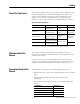
Commissioning Your Ultra3000 Drive 11. Using this table, determine the sequence of these three inputs that correspond to the preset velocity entered. Preset Selects Select up to 64 locations via preselect inputs 5…0 by using BCD format. (codes for preset selects 1 and 0 are shown) Binary Code Selected Preset or Index 5 4 3 2 1 0 0 0 0 0 0 0 Preset 0 or Index 0 is selected. 0 0 0 0 0 1 Preset 1 or Index 1 is selected. 0 0 0 0 1 0 Preset 2 or Index 2 is selected.
Commissioning Your Ultra3000 Drive 37 14. Click Setup. The Monitor Setup dialog opens. 15. In the Monitor Setup dialog, check Velocity Signals. 16. Click OK. The Monitor Status dialog closes and the setup changes take affect. 17. Observe that Velocity - Command matches what was entered in Preset Velocity 0. 18. Observe the Velocity - Motor Feedback continually updating to maintain the commanded velocity. 19. Apply 12…24V dc to Preset Select 0 configured as Digital Input 8 (CN1-38).
Commissioning Your Ultra3000 Drive 3. Click the current setting and use the pull-down menu to change the Operation Mode to Preset Position. 4. Close the Drive Branch dialog. 5. Expand the Mode Configuration branch and double-click Preset. The Preset setup dialog opens. 6. Enter the Preset Velocity values as shown in the table above or otherwise appropriate to your application. 7. Double-click the Digital Inputs branch. 8.
Commissioning Your Ultra3000 Drive 39 9. Using this table, determine the sequence of these three inputs that correspond to the preset positions entered. Preset Selects Select up to 64 locations via preselect inputs 5…0 by using BCD format. (codes for preset selects 1 and 0 are shown) Binary Code Selected Preset or Index 5 4 3 2 1 0 0 0 0 0 0 0 Preset 0 or Index 0 is selected. 0 0 0 0 0 1 Preset 1 or Index 1 is selected. 0 0 0 0 1 0 Preset 2 or Index 2 is selected.
Commissioning Your Ultra3000 Drive 12. In the Monitor Setup dialog, check Position Signals. 13. Click OK. The Monitor Status dialog closes and the setup changes take affect. 14. Apply 12…24V dc to input 1. Input 1 was configured as Drive Enable in a previous step. a. Verify the toolbar Enable icon is active, indicating the drive is enabled. b. Verify the Drive Enabled lamp is ON (yellow) c. If none of the Preset Selects are ON, observe the motor move to Preset Position 0.
Commissioning Your Ultra3000 Drive 41 3. Click the current setting and use the pull-down menu to change the Operation Mode to Follower: Auxiliary Encoder. 4. Close the Drive Branch dialog. 5. Expand the Mode Configuration branch. 6. Double-click Follower. 7. Enter the Gear Ratio preset values as shown in the table below or according to your specific application. 8. Close the Mode Configuration dialog. 9. Double-click the Digital Inputs branch. 10. Use the pull-down menu to change the input values.
Commissioning Your Ultra3000 Drive 11. Using this table, determine the sequence of these three inputs that correspond to the preset gear ratios entered. Preset Selects Select up to 64 locations via preselect inputs 5…0 by using BCD format. (codes for preset selects 1 and 0 are shown) Binary Code Selected Preset or Index 5 4 3 2 1 0 0 0 0 0 0 0 Preset 0 or Index 0 is selected. 0 0 0 0 0 1 Preset 1 or Index 1 is selected. 0 0 0 0 1 0 Preset 2 or Index 2 is selected.
Commissioning Your Ultra3000 Drive 43 15. Click OK. The Monitor Status dialog closes and the setup changes take affect. 16. Apply 12…24V dc to input 1. Input 1 was configured as Drive Enable in a previous step. a. Verify the toolbar Enable icon is active, indicating the drive is enabled. b. Verify the Drive Enabled lamp is ON (yellow) c. If none of the Presets are ON, move the auxiliary encoder and observe the motor rotate at Preset 0 Gear Ratio or 1:1. 17.
Commissioning Your Ultra3000 Drive Incremental Indexing (indexing move) This procedure assumes you have applied power to your indexing drive, the Ultraware software is running, the drive is detected, and you have tested a motor. In this procedure you will run the drive in Incremental Indexing mode. Refer to the Ultraware User Manual, publication 2098-UM001, for more information on incremental indexing moves. Follow these steps to set parameters for an incremental indexing move. 1.
Commissioning Your Ultra3000 Drive 45 10. Use the pull-down menu to change the input values. 11. Close the Digital Inputs dialog. 12. Double-click the Digital Outputs branch. 13. Use the pull-down menu to change the output values. 14. Close the Digital Outputs dialog.
Commissioning Your Ultra3000 Drive Follow these steps to verify the number of indexing moves by using drive signals. 1. Double-click the Monitor branch. 2. Click Setup. 3. Expand the Mode Configuration branch/the Indexing branch/and check Batch Count. 4. Click OK. 5. Apply 12…24V dc to input 1. Input 1 was configured as Drive Enable in a previous step. 6. Apply 12…24V dc to input 3 to the indexing move. 7. Double-click the Monitor branch and watch Batch Count count down from 10 to 0. 8.
Commissioning Your Ultra3000 Drive 47 Follow these steps to use the stop indexing feature. 1. Apply 12…24V dc to input 1. Input 1 was configured as Drive Enable in a previous step. 2. Apply 12…24V dc to input 3 to the indexing move. 3. Apply 12…24V dc to input 4 and verify that the indexing move has stopped. 4. Apply 12…24V dc to input 3 (again) and verify the original indexing move is re-initiated. 5. Apply 12…24V dc to input 5 and verify the index move is paused. 6.
Commissioning Your Ultra3000 Drive Absolute Indexing (indexing move) This procedure assumes you have applied power to your indexing drive, the Ultraware software is running, the drive is detected, and you have tested a motor. In this procedure you will run the drive in Absolute Indexing mode. Refer to the Ultraware User Manual, publication 2098-UM001, for more information on absolute indexing moves. Follow these steps to set parameters for an absolute indexing move. 1. Double-click the U3k icon.
Commissioning Your Ultra3000 Drive 49 8. Enter the Index 1 parameter values as shown in the table below. 9. Close the Indexing Parameters dialog. 10. Expand the Mode Configuration branch. 11. Double-click Homing. 12. Enter the Homing parameter values as shown in the table below. 13. Close the Homing Parameters dialog. 14. Close the Mode Configuration dialog. 15. Double-click the Digital Inputs branch. 16. Use the pull-down menu to change the input values. 17. Close the Digital Inputs dialog.
Commissioning Your Ultra3000 Drive Follow these steps to use digital outputs to indicate an event has occurred. 1. Double-click the Digital Outputs branch. 2. Use the pull-down menu to change the output values. 3. Close the Digital Outputs dialog. 4. Apply 12…24V dc to input 1. Input 1 was configured as Drive Enable in a previous step. 5. Apply 12…24V dc to input 3 (momentarily) to start the homing routine. 6. Apply 12…24V dc to input 4 (momentarily) to simulate a homing sensor.
Commissioning Your Ultra3000 Drive 51 11. Turn off input 5. 12. Apply 12…24V dc to input 4 (momentarily again) to restart the indexing move. 13. Turn off input 4. 14. Apply 12…24V dc to input 7 to pause the indexing move. 15. Remove the 12…24V dc and observe the index move continue. 16. Close the dialogs. 17. Remove the 12…24V dc (Drive Enable) from input 1.
Commissioning Your Ultra3000 Drive Configuring Your Ultra3000 Drive with RSLogix 5000 Software In this section you will configure your Ultra3000 drive by using Ultraware software, configure the Logix analog motion module by using RSLogix 5000 software, and test/tune your axis. Configure Your Ultra3000 Drive Follow these steps to configure your Ultra3000 drive. 1. Apply power to your Ultra3000 drive Refer to the section Apply Power To Your Ultra3000 Drive. 2.
Commissioning Your Ultra3000 Drive 53 Configuring Your Logix Analog Motion Module This procedure assumes that you have finished configuring your Ultra3000 drive. For help using RSLogix 5000 software as it applies to configuring the Logix analog modules, refer to Additional Resources on page 8. Configure Your Logix Controller Follow these steps to configure your Logix controller. 1. Apply power to your Logix chassis containing the analog motion module and open your RSLogix 5000 software. 2.
Commissioning Your Ultra3000 Drive The Controller Properties dialog opens. 6. Click the Date/Time tab. 7. Check the Make this controller the Coordinated System Time master checkbox. IMPORTANT 8. Click OK. Publication 2098-IN005C-EN-P — March 2008 Only one Logix processor can be assigned as the Coordinated System Time master.
Commissioning Your Ultra3000 Drive 55 Configure Your Logix Module Follow these steps to configure your Logix module. 1. In the Explorer dialog, right-click I/O Configuration and choose New Module. The Select Module dialog opens. 2. Expand the Motion category and select 1756-M02AE, 1756-HYD02, 1756-M02AS, or 1784-PM02AE as appropriate for your actual hardware configuration. 3. Click OK. Your new module appears under the I/O Configuration folder in the Explorer dialog and the New Module dialog opens. 4.
Commissioning Your Ultra3000 Drive 6. Click the Associated Axes tab. 7. Click New Axis. The New Tag dialog opens. 8. Configure the new tag. a. In the Name box, enter your axis name. b. From the Data Type pull-down menu, choose AXIS_SERVO. 9. Click OK. 10. From the Channel 0 pull-down menu, choose your axis. 11. Click OK.
Commissioning Your Ultra3000 Drive 57 Configure the Motion Group Follow these steps to configure the motion group. 1. In the Explorer dialog, right-click Motion Groups and choose New Motion Group. The New Tag dialog opens. 2. In the Name box, enter your motion group name. 3. Click OK. The new group appears under the Motion Group folder. 4. Right-click the new motion group and choose Properties. The Motion Group Properties dialog opens. 5.
Commissioning Your Ultra3000 Drive Configure Axis Properties Follow these steps to configure axis properties. 1. In the Explorer dialog, right-click an axis and choose Properties. The Axis Properties dialog opens. 2. Click the Servo tab. a. From the External Drive Configuration pull-down menu choose Torque. In Torque mode, both position and velocity loops are closed in the Logix controller. In Velocity mode, only the position loop is closed in the Logix controller. b.
Commissioning Your Ultra3000 Drive 59 Testing and Tuning Your Axis This procedure assumes that you have configured your Ultra3000 drive and the analog motion module. IMPORTANT Before proceeding with testing and tuning your axis, verify that the seven-segment status indicator is actively cycling in a full circle. For help using RSLogix 5000 software as it applies to the analog Logix modules, refer to Additional Resources on page 8. Test Your Axis Follow these steps to test your axis. 1.
Commissioning Your Ultra3000 Drive 4. In the Test Increment box, enter 2.0 as the number of revolutions for the test (or another number more appropriate for your application). Test Description Test Marker Verifies marker detection capability as you rotate the motor shaft. Test Feedback Verifies feedback connections are wired correctly as you rotate the motor shaft. Test Command & Feedback Verifies motor power and feedback connections are wired correctly as you command the motor to rotate.
Commissioning Your Ultra3000 Drive 61 9. Determine if your test completed successfully. If Then Your test completes successfully, this dialog appears. 1. Click OK. 2. Remove Drive Enable signal (CN1-31). 3. Go to Tune Your Axis. Your test failed, this dialog appears. 1. Click OK. 2. Verify that the main three-phase bus power is up. 3. Verify that the Drive Enable signal (CN1-31) is applied to the axis you are testing. 4. Verify conversion constant entered in the Conversion tab. 5.
Commissioning Your Ultra3000 Drive Tune Your Axis Follow these steps to tune your axis. 1. Verify that the load is still removed from the axis being tuned. ATTENTION To reduce the possibility of unpredictable motor response, tune your motor with the load removed first, then reattach the load and perform the tuning procedure again to provide an accurate operational response. 2. Click the Tune tab. 3. In the Travel Limit and Speed boxes, enter values. In this example, Travel Limit = 5 and Speed = 2.
Commissioning Your Ultra3000 Drive 63 7. Click Start Tuning to auto-tune your axis. The Online Command - Tune Servo dialog opens. When the test completes, the Command Status changes from Executing to Command Complete. 8. Click OK. The Tune Bandwidth dialog opens. Actual bandwidth values (Hz) depend on your application and may require adjustment once motor and load are connected. Record your bandwidth data for future reference. 9. Click OK. The Online Command - Apply Tune dialog opens.
Commissioning Your Ultra3000 Drive If Then Your test completes successfully, this dialog appears. 1. Click OK. 2. Remove Drive Enable (Input 1) signal (CN1-31) applied earlier. 3. You are finished tuning your Ultra3000 drive. Your test failed, this dialog appears. 1. Click OK. 2. Make an adjustment to motor velocity. 3. Refer to the appropriate Logix motion module setup and configuration manual for more information. 4. Return to step 7 and run the test again.
Commissioning Your Ultra3000 Drive Configuring Your Ultra3000 Drive with SERCOS 65 The procedures in this section are listed in this table and apply to Ultra3000-SE drives with SERCOS interface.
Commissioning Your Ultra3000 Drive Use this figure to locate the front panel connections on the Ultra3000-SE 230V drives (500W, 1 kW, and 2 kW).
Commissioning Your Ultra3000 Drive 67 Use this figure to locate the front panel connections on the Ultra3000-SE 230V drive (3 kW).
Commissioning Your Ultra3000 Drive Use this figure to locate the front panel connections on the Ultra3000-SE 230V drives (7.5 and 15 kW).
Commissioning Your Ultra3000 Drive 69 Use this figure to locate the front panel connections on the Ultra3000-SE 460V drives (3 kW, 5 kW, 10 kW, 15 kW, and 22 kW).
Commissioning Your Ultra3000 Drive Configure Your Ultra3000-SE Drive Follow these steps to configure your Ultra3000-SE drive. 1. Verify that there is no power applied to the drive and that the SERCOS fiber-optic cables are correctly plugged into the Tx and Rx connectors. To verify your fiber-optic cable connections, refer to Fiber-optic Ring Connections on page 71. 2. Set the node address for each drive in your system. Valid node addresses are 01…99.
Commissioning Your Ultra3000 Drive 71 5. If using Overtravel inputs, verify that 12…24V dc is tied to CN1-37 and CN1-38. IMPORTANT Without CN1-37 and CN1-38 inputs applied, the drive/ system will fault.
Commissioning Your Ultra3000 Drive Configuring Your Logix SERCOS interface Module This procedure assumes that you have configured the Ultra3000-SE communication rate. IMPORTANT In order for the Ultra3000 drive to communicate with the SERCOS interface module (indicated by the three status indicators on the module going solid green), your RSLogix 5000 software must be version 11.0 or later.
Commissioning Your Ultra3000 Drive 73 4. Click OK. 5. From the Edit menu, choose Controller Properties. The Controller Properties dialog opens. 6. Click the Date/Time tab. 7. Check the Make this controller the Coordinated System Time master checkbox. IMPORTANT Only one Logix processor can be assigned as the Coordinated System Time master. 8. Click OK. Configure Your Logix Module Follow these steps to configure your Logix module. 1.
Commissioning Your Ultra3000 Drive The New Module dialog opens. 4. Configure the new module. a. In the Name box, name your file. b. In the Slot box, enter the slot where your module resides. c. From the Electronic Keying pull-down menu, choose an electronic keying option (choose Disable Keying if unsure). d. Check the Open Module Properties checkbox. 5. Click OK. Your new module appears under the I/O Configuration folder in the Explorer dialog and the Module Properties dialog opens. 6.
Commissioning Your Ultra3000 Drive 75 7. Verify that the Data Rate setting matches the Data Rate (communication rate) switch setting on the Ultra3000-SE drive. 8. Set the Cycle Time according to this table. Data Rate 4 Mbps Number of Axes Cycle Time Up to 4 1 ms Up to 8 2 ms No support for axes 9…16 8 Mbps Up to 8 1 ms Up to 16 2 ms The number of axes/module is limited to the number of axes as shown in step 6. 9. Verify that Transmit Power is set to High. 10. Set Transition to Phase.
Commissioning Your Ultra3000 Drive The New Module dialog opens. 4. Configure the new module. a. In the Name box, enter your module name. b. In the Node box, enter the node address. Set the node address in the software to match the node address setting on the drive. Refer to Configure Your Ultra3000-SE Drive, step 2, on page 70. c. From the Electronic Keying pull-down menu, choose an electronic keying option (choose Disable Keying if unsure). d. Check the Open Module Properties checkbox. 5. Click OK.
Commissioning Your Ultra3000 Drive 77 The New Tag dialog opens. 8. Configure the new tag. a. In the Name box, enter your module name. b. In the Data Type pull-down menu, choose AXIS_SERVO_DRIVE. 9. Click OK. The axis appears under the Ungrouped Axes folder in the Explorer dialog. 10. From the Node 1 pull-down menu, choose the node address for your axis. 11. Click OK.
Commissioning Your Ultra3000 Drive Configure the Motion Group Follow these steps to configure the motion group. 1. In the Explorer dialog, right-click Motion Groups and choose New Motion Group. The New Tag dialog opens. 2. In the Name box, enter the new motion group name. 3. Click OK. The new group appears under Motion Group folder. 4. Right-click the new motion group and choose Properties. The Motion Group Properties dialog opens. 5.
Commissioning Your Ultra3000 Drive 79 Configure Axis Properties Follow these steps to configure axis properties. 1. In the Explorer dialog, right-click an axis and choose Properties. The Axis Properties dialog opens. 2. Click the Drive/Motor tab. a. From the Amplifier Catalog Number pull-down menu, choose the Ultra3000 amplifier (2098-DSD-xxx-SE or 2098-DSD-HVxxx-SE). b. Click Change Catalog to set the motor catalog number.
Commissioning Your Ultra3000 Drive 6. Click the Fault Actions tab. TIP For more information on setting fault limits, refer to Appendix C, Minimizing the Effects of Feedback Signal Loss on page 141. 7. Click the Set Custom Stop Action. The Custom Stop Action Attributes dialog opens. 8. Set the appropriate values. a. Set the Brake Engage Delay Time. Use this setting to hold motor torque on load until the delay time has expired (brake is engaged). b. Set the Brake Release Delay Time.
Commissioning Your Ultra3000 Drive 81 Apply Power to Your Ultra3000 Drive with SERCOS This procedure assumes that you have configured your Ultra3000-SE drive and your SERCOS interface module. ATTENTION High voltage exists in ac line filters. The filter must be grounded properly before applying power. Filter capacitors retain high voltages after power removal. Before handling the equipment, voltages should be measured to determine safe levels.
Commissioning Your Ultra3000 Drive The status indicator cycles through SERCOS phases until final configuration (phase 4) is reached. Seven-segment Status Indicator Status Do This Actively cycling (phase 0) The drive is looking for a closed SERCOS ring. Wait for phase 1 or take corrective action until you reach phase 1. Check fiber-optic connections. Displaying a fixed 1 (phase 1) The drive is looking for active nodes. Wait for phase 2 or take corrective action until you reach phase 2.
Commissioning Your Ultra3000 Drive 83 Testing and Tuning Your Axis This procedure assumes that you have configured your Ultra3000-SE drive, your SERCOS interface module, and applied power to the system. IMPORTANT Before proceeding with testing and tuning your axis, verify that the Ultra3000-SE status indicators are as described in this table. Status Indicator Indication Status Seven-segment Displaying a fixed 4 (phase 4) The drive is ready. Module Flashing green The drive is disabled.
Commissioning Your Ultra3000 Drive 4. In the Test Increment box, enter 2.0 as the number of revolutions for the test (or another number more appropriate for your application). Test Description Test Marker Verifies marker detection capability as you rotate the motor shaft. Test Feedback Verifies feedback connections are wired correctly as you rotate the motor shaft. Test Command & Feedback Verifies motor power and feedback connections are wired correctly as you command the motor to rotate.
Commissioning Your Ultra3000 Drive 85 8. Click OK. 9. Determine if your test completed successfully. If Then Your test completes successfully, this dialog appears. 1. Click OK. 2. Remove Drive Enable signal (CN1-31). 3. Go to Tune Your Axis on page 86. Your test failed, this dialog appears. 1. Click OK. 2. Verify that the main three-phase bus power is up. 3. Verify that the Drive Enable signal (CN1-31) is applied to the axis you are testing. 4.
Commissioning Your Ultra3000 Drive Tune Your Axis Follow these steps to tune your axis. 1. Verify that the load is still removed from the axis being tuned. ATTENTION To reduce the possibility of unpredictable motor response, tune your motor with the load removed first, then reattach the load and perform the tuning procedure again to provide an accurate operational response. 2. Click the Tune tab. 3. In the Travel Limit and Speed boxes, enter appropriate values.
Commissioning Your Ultra3000 Drive 87 7. Click Start Tuning to auto-tune your axis. The Online Command - Tune Servo dialog opens. When the test completes, the Command Status changes from Executing to Command Complete. 8. Click OK. The Tune Bandwidth dialog opens. Actual bandwidth values (Hz) depend on your application and may require adjustment once motor and load are connected. 9. Record your bandwidth data for future reference. 10. Click OK. The Online Command - Apply Tune dialog opens.
Commissioning Your Ultra3000 Drive If Then Your test completes successfully, this dialog appears. 1. Click OK. 2. Remove Drive Enable (Input 1) signal (CN1-31) applied earlier. 3. You are finished tuning your axis. Your test failed, this dialog appears. 1. Click OK. 2. Make an adjustment to motor velocity. 3. Refer to appropriate Logix motion module setup and configuration manual for more information. 4. Return to step 7 and run the test again.
Commissioning Your Ultra3000 Drive Configuring Your Ultra3000 Drive with DeviceNet 89 The procedures in this section are listed in this table and apply to Ultra3000-DN drives with indexing. Ultra3000 Drive Configuration Procedures Procedure Page Configure Your Ultra3000 Drive with DeviceNet 93 Apply Power to Your Ultra3000 Drive with DeviceNet 94 These procedures assume you have completed wiring the DeviceNet interface connector on your Ultra3000-DN drive.
Commissioning Your Ultra3000 Drive Use this figure to locate the front panel connections on the Ultra3000-DN 230V drives (3 kW).
Commissioning Your Ultra3000 Drive 91 Use this figure to locate the front panel connections on the Ultra3000-DN 230V drives (7.5 and 15 kW).
Commissioning Your Ultra3000 Drive Use this figure to locate the front panel connections on the Ultra3000-DN 460V drives (3 kW, 5 kW, 10 kW, 15 kW, and 22 kW).
Commissioning Your Ultra3000 Drive 93 Configure Your Ultra3000 Drive with DeviceNet Follow these steps to configure your Ultra3000-DN drive. 1. Verify that there is no power applied to the drive and that the DeviceNet cable is connected. Refer to the figures on pages 89…92 for switch locations. 2. Set the node address for each drive in your system. Valid node addresses are 00…63 and PGM. The MSD rotary switch sets the most significant digit and the LSD rotary switch sets the least significant digit.
Commissioning Your Ultra3000 Drive Apply Power to Your Ultra3000 Drive with DeviceNet This procedure assumes you have wired your Ultra3000-DN system, verified the wiring, and are ready to begin using Ultraware software. ATTENTION High voltage exists in ac line filters. The filter must be grounded properly before applying power. Filter capacitors retain high voltages after power removal. Before handling the equipment, voltages should be measured to determine safe levels.
Commissioning Your Ultra3000 Drive 95 4. Observe the module status indicator. Module Status Indicator Status Do This Steady green The drive is ready. Go to step 5. Not steady green The drive is faulted. Go to DeviceNet Module Status Indicator on page 109. 5. Observe the network status indicator. Network Status Indicator Status Do This Off Establishing communication with network. Wait for flashing or steady green. Flashing or steady green Communication is ready. Go to step .
Commissioning Your Ultra3000 Drive Publication 2098-IN005C-EN-P — March 2008
Chapter 2 Troubleshooting Your Ultra3000 Servo Drive Introduction Safety Precautions This chapter provides troubleshooting tables for your Ultra3000 servo drive. Topic Page Safety Precautions 97 General Troubleshooting 98 Troubleshooting for SERCOS Drives 104 Troubleshooting for DeviceNet Drives 109 Observe the following safety precautions when troubleshooting your Ultra3000 servo drive. ATTENTION DC bus capacitors may retain hazardous voltages after input power has been removed.
Troubleshooting Your Ultra3000 Servo Drive General Troubleshooting Refer to the Error Codes section below to identify problems, potential causes, and appropriate actions to resolve the problems. If problems persist after attempting to troubleshoot the system, please contact your Rockwell Automation sales representative for further assistance.
Troubleshooting Your Ultra3000 Servo Drive Error Code E02 Problem or Symptom Possible Cause Action/Solution Velocity Exceeds Position Rollover /2 The velocity command or feedback exceeds half the machine cycle length per millisecond (applies only when the machine cycle position rollover is enabled). Increase machine cycle size or reduce velocity profile.
Troubleshooting Your Ultra3000 Servo Drive Error Code Problem or Symptom E10 E11 Bus Overvoltage Illegal Hall State Possible Cause Action/Solution Excessive regeneration of power. • Change the deceleration or motion profile. When the motor is driven by an external mechanical power source, it may regenerate too much peak energy through the Ultra3000’s power supply. The system faults to save itself from an overload. • Use a larger system (motor and Ultra3000). • Use a resistive shunt.
Troubleshooting Your Ultra3000 Servo Drive Error Code Problem or Symptom Possible Cause 101 Action/Solution • Replace the motor/encoder. • Use shielded cables with twisted pair wires. • Route the feedback away from potential noise sources. • Check the system grounds. E20 Motor Encoder State Error The motor encoder encountered an illegal transition. • Verify that the unbuffered encoder signals are not subjected to EMI in the CN1 cable.
Troubleshooting Your Ultra3000 Servo Drive Error Code E28 E29 Problem or Symptom Possible Cause Motor Parameter Error Parameter loaded from smart encoder or received from SERCOS controller is incompatible with the drive. Encoder Output Frequency Exceeded Encoder output frequency exceeds the maximum user-specified value. This only applies when the encoder output is synthesized by the drive. Action/Solution • Select a different motor through the SERCOS controller. • Select a different motor.
Troubleshooting Your Ultra3000 Servo Drive Error Code Problem or Symptom Possible Cause 103 Action/Solution • Verify that there are no impediments to motion at startup, such as hard limits. E39 Self-sensing Commutation Startup Error Motion required for self-sensing startup commutation was obstructed. • Increase self-sensing current if high friction or load conditions exist. • Check motor or encoder wiring using wiring diagnostics.
Troubleshooting Your Ultra3000 Servo Drive Troubleshooting for SERCOS Drives These troubleshooting tables apply to Ultra3000-SE drives (2098-DSD-xxx-SE and 2098-DSD-HVxxx-SE). SERCOS Module Status Indicator SERCOS Module Status Indicator Status Potential Cause Possible Resolution Steady green Normal Drive is enabled. Normal operation when drive is enabled. Flashing green Standby Drive is not enabled. Normal operation when drive is disabled.
Troubleshooting Your Ultra3000 Servo Drive 105 Understanding Drive Fault Behavior The following RSLogix 5000 fault actions are configurable from the Axis Properties dialog, Fault Actions tab. RSLogix 5000 Drive Fault Action Definitions Drive Fault Action Definition Shutdown The drive disables and the contactor enable relay opens. Uncontrolled stop, motor coasts to a stop. Disable Drive The drive is disabled. Uncontrolled Stop, motor coasts to a stop. Stop Motion N/A. Drive continues to operate.
Troubleshooting Your Ultra3000 Servo Drive When a fault is detected, the seven-segment status indicator displays E followed by the flashing two-digit error code, one digit at a time. This is repeated until the fault is cleared.
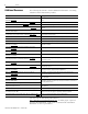
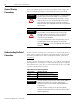
Troubleshooting Your Ultra3000 Servo Drive Software Fault Message 107 Error Code Description Drive Fault Action/Attribute RSLogix 5000 Programmable Fault Action? DriveHardFault (User-specified Current Fault) E17 User-specified average current level has been exceeded. DISABLE NO OverspeedFault (Overspeed Fault) E18 Motor speed has exceeded 125% of maximum rated speed. DISABLE NO PositionErrorFault (Excess Position Error) E19 Axis position error limit has been exceeded.
Troubleshooting Your Ultra3000 Servo Drive Software Fault Message Error Code Description Drive Fault Action/Attribute RSLogix 5000 Programmable Fault Action? DriveHardFault (Precharge Fault) E35 The converter pre-charge cycle has failed. DISABLE NO DriveHardFault (Power Circuitry Overtemperature) E36 Excessive heat exists in the power circuitry. DISABLE NO DriveHardFault (AC Line Loss) E37 One or more phases of the input ac power is missing.
Troubleshooting Your Ultra3000 Servo Drive Troubleshooting for DeviceNet Drives 109 These troubleshooting tables apply to Ultra3000-DN drives (2098-DSD-xxx-DN, 2098-DSD-xxxX-DN, 2098-DSD-HVxxx-DN, or 2098-DSD-HVxxxX-DN). DeviceNet Module Status Indicator Module Status Indicator Status Potential Cause Possible Resolution Off Not powered No power There is no power going to the device. Steady-green Operational Normal operation Normal operation - no action needed.
Troubleshooting Your Ultra3000 Servo Drive Node Problems Give particular attention to the task of setting initial addresses and data rates. Survey the network to ensure all assignments are known. Some nodes can be logically assigned to a group of devices, but physically located away from those devices. One incorrect node can cause other nodes to appear to be bus-off (steady-red indicator).
Troubleshooting Your Ultra3000 Servo Drive 111 Scanner Problems If using a scanner, check the scan list, data rate, and addresses of devices. Verify series and revision of the scanner is the latest. If the scanner is bus-off, recycle the 24V supply and then reset the scanner. If the scanner goes bus-off again, the problem is some combination of these issues.
Troubleshooting Your Ultra3000 Servo Drive Cable Installation and Design Problems Cable installation and design refers to the physical layout and connections on the network. Walk the network if possible to determine the actual layout and connections. Network management software displays only a logical record of the network. Make sure you have a diagram of the physical layout and a record of the information in these tables. Cable Checks Power Checks Number of nodes.
Appendix A Interconnect Diagrams Introduction 113 This appendix provides you with interconnect diagrams for your Ultra3000 servo drive.
Interconnect Diagrams Wiring Examples This appendix provides wiring examples to assist you in wiring the Ultra3000 drive system. The notes in this table apply to the power, shunt, motor, actuator, and control string interconnect diagrams. ATTENTION The National Electrical Code and local electrical codes take precedence over the values and methods provided. Implementation of these codes are the responsibility of the machine builder.
Interconnect Diagrams 115 Power Interconnect Diagrams This is the power wiring diagram with 24V dc control string for 2098-DSD-005x-xx, 2098-DSD-010x-xx, and 2098-DSD-020x-xx Ultra3000 drives (non-SERCOS drives only). To avoid a separate 5V dc auxiliary logic power supply, the 24V to 5V converter breakout board (catalog number 2090-U3CBB-DMxx) is used to wire the control interface (CN1) connector. For the control string diagram with 120V ac input refer to the figure on page 128.
Interconnect Diagrams This is the power wiring diagram with 24V dc control string for the 2098-DSD-030x-xx drive (non-SERCOS drives only). For the control string diagram with 120V ac input refer to the figure on page 129. For SERCOS drives, input line contactor is part of the PLC program and output control.
Interconnect Diagrams 117 This is the power wiring diagram with 24V dc control string for 2098-DSD-075x-xx and 2098-DSD-150x-xx Ultra3000 drives (non-SERCOS drives only). For the control string diagram with 120V ac input refer to the figure on page 130. For SERCOS drives, input line contactor is part of the PLC program and output control.
Interconnect Diagrams This is the power wiring diagram with 24V dc control string for 2098-DSD-HVxxx-xx and 2098-DSD-HVxxxX-xx Ultra3000 drives. For the control string diagram with 120V ac input refer to the figure on page 130.
Interconnect Diagrams 119 Shunt Module Interconnect Diagrams This section contains the interconnect diagrams for Ultra3000 drives with active and passive shunt modules.
Interconnect Diagrams External Passive Shunt (single-shunt) Diagram External Passive Shunt Module DC+ COL 2098-DSD-030x-xx, 2098-DSD-075x-xx, 2098-DSD-150x-xx, 2098-DSD-HVxxx-xx, and 2098-DSD-HVxxxX-xx Ultra3000 Digital Servo Drives TB2 1 External Passive Shunt Resistor Connections 2 3 In this figure, the 2098-DSD-150x-xx Ultra3000 drive is wired with two external passive shunt resistors.
Interconnect Diagrams 121 In this figure, the 2098-DSD-HV150x-xx or 2098-DSD-HV220x-xx Ultra3000 drive is wired to a Bonitron shunt module. External Passive Shunt (Bonitron shunt) Diagram 2098-DSD-HV150x-xx or 2098-DSD-HV220x-xx Ultra3000 Digital Servo Drives TB2 1 2 Shunt Wiring Methods: Twisted pair in conduit (1st choice). Shielded twisted pair (2nd choice). Twisted pair, 2 twists per foot min. (3rd choice). External Passive Shunt Resistor Connections 3 Maximum Length: 3.05 m (10 ft).
Interconnect Diagrams Ultra3000 Drives/Rotary Motors and Actuators Wiring Examples Wiring Examples with MPL-A and MPG-A (MP-Series) Motors/Actuators 2090-XXNPMP-xxSxx Motor Power Cable Note 12 MPL-A3xx…MPL-A5xx, and MPG-Axxx (230V) Servo Motors with High Resolution Feedback Ultra3000 230V Drive Note 13 D Blue C B W A U Black Brown Motor Feedback (15-pin) Connector CN2 Motor Feedback (CN2) Connector Green/Yellow V GND Three-phase Motor Power Motor Feedback BRN BLK BLU 2090-UXNBMP-18Sxx
Interconnect Diagrams 123 Wiring Examples with MPL-B, MPG-B, and 1326AB Motors/Actuators MPL-B3xx…MPL-B9xx, MPG-Bxx, or 1326AB (M2L/S2L) (460V) Servo Motors with High Resolution Feedback 2090-XXNPMP-xxSxx Motor Power Cable Note 12 Ultra3000 460V Drive Note 14 Green/Yellow D Blue C B W A U Black Brown Motor Feedback (15-pin) Connector CN2 V Motor Feedback (CN2) Connector GND Three-phase Motor Power Motor Feedback 2090-UXNBMP-18Sxx Brake Cable Note 12 Black C 43 BLU W V U BLK BRN Note 21
Interconnect Diagrams Wiring Examples with MPL-A/B, MPF-A/B, and MPS-A/B (MP-Series) Motors MPL-A/B15xx and MPL-A/B2xx, MPF-A/Bxxx and MPS-A/Bxxx Servo Motors with High Resolution Feedback 2090-XXNPMF-xxSxx Motor Power Cable Note 12, 16, 20 Green/Yellow Ultra3000 Drive Notes 13, 14 Blue Motor Feedback (15-pin) Connector CN2 Motor Feedback (CN2) Connector D/ Black C/W B/V Brown A/U W GND V Three-phase U Motor Power Motor Feedback 43 BRN U V W BLK BLU Note 21 Black Control Interface
Interconnect Diagrams 125 Wiring Example with TLY-A (TL-Series) Motors Ultra3000 (230V) Drive TLY-Axxxx-H (230V) Servo Motors with Incremental Feedback Note 13 0 1 2 3 4 5 6 7 8 9 10 11 12 13 14 15 Motor Power (TB1) Connector 4 3 2 1 W V U Green/Yellow 5 Blue 3 2 Black Brown 1 W GND V Three-phase U Motor Power 2090-CPBM6DF-16AAxx Motor Power Cable Note 12, 16 Motor Feedback (CN2) Connector 2090-CPWM6DF-16AAxx cable for motor without brake.
Interconnect Diagrams Wiring Examples with F-Series (230V) Motors 2090-XXNPHF-xxSxx or 2090-UXNPAHF-xxSxx Motor Power Cable Note 12 F-Series (230V) Servo Motors with Incremental Feedback Ultra3000 230V Drive Green/Yellow D Note 13 Blue C B W A U Black Brown Motor Feedback (15-pin) Connector CN2 V GND Three-phase Motor Power Motor Feedback 9101-0330 Brake Cable Connector Kit Note 12 BRN BLK BLU 43 U V W Black B Note 21 A Control Interface 44 White (44-pin) Connector CN1 COM +24V GN
Interconnect Diagrams 127 Ultra3000 Drives/Linear Actuators Wiring Examples Wiring Example with MPAS-A/B (MP-Series) Linear Stages MPAS-A/Bxxxxx-VxxSxA Ballscrew Linear Stages with High Resolution Feedback 2090-XXNPMF-xxSxx Motor Power Cable Note 12, 16 Green/Yellow Ultra3000 Drive Notes 13, 14 Blue Motor Feedback (15-pin) Connector CN2 Motor Feedback (CN2) Connector D C Black B Brown A W GND V Three-phase U Motor Power Motor Feedback 43 BRN U V W BLK BLU Note 21 Control Interface 44 (
Interconnect Diagrams Control String Examples (120V ac) This section provides information to assist you in using the configurable Drive Ready output in a control string with 120V ac input voltage. In this example, the 2098-DSD-005x-xx, 2098-DSD-010x-xx, or 2098-DSD-020x-xx Ultra3000 drive is wired to the 120V ac control string. Implementation of safety circuits and risk assessment is the responsibility of the machine builder.
Interconnect Diagrams 129 In this example, the 2098-DSD-030x-xx Ultra3000 drive is wired to the 120V ac control string. ATTENTION Implementation of safety circuits and risk assessment is the responsibility of the machine builder. Please reference international standards EN1050 and EN954 estimation and safety performance categories. For more information refer to Understanding the Machinery Directive, publication SHB-900.
Interconnect Diagrams In this example, the 2098-DSD-075x-xx, 2098-DSD-150x-xx, 2098-DSD-HVxxx-xx, and 2098-DSD-HVxxxX-xx Ultra3000 drive is wired to the 120V ac control string. ATTENTION Implementation of safety circuits and risk assessment is the responsibility of the machine builder. Please reference international standards EN1050 and EN954 estimation and safety performance categories. For more information refer to Understanding the Machinery Directive, publication SHB-900.
Interconnect Diagrams Controlling a Brake Example 131 The relay output of the Ultra3000 drive (pins CN1-43 and CN1-44) is suitable for directly controlling a motor brake, subject to the relay voltage limit of 30V dc, and the relay current limit of 1 A dc. For brake requirements outside of these limits, an external relay must be used. If a transistor output is used, a control relay is also required. Coil Currents Rated at < 1.
Interconnect Diagrams A separate power source is required to disengage the brake. Removing power causes the brake to engage, but may also cause electrical arcing to occur at the relay contacts until the brake power dissipates. A customer-supplied diode or metal oxide varistor (MOV) is recommended to prevent arcing. Use of an MOV can also reduce the time to mechanically engage the brake. IMPORTANT Electrical arcing may occur at the relay contacts until the brake power dissipates.
Interconnect Diagrams Ultra3000 Drive to Logix Analog Module Diagrams 133 This section provides information to assist you in wiring the Ultra3000 drive CN1 (44-pin) cable connector with either the ControlLogix 1756-M02AE servo module or SoftLogix 1784-PM02AE motion card. Use the 2090-U3AE-D44xx control interface cable (shown below) when connecting two Ultra3000 drives to the 1756-M02AE servo module. This cable includes the 1756-TBCH pre-wired terminal block. Refer to for the interconnect diagram.
Interconnect Diagrams Ultra3000 Drive to ControlLogix Servo Module Interconnect Diagram 43 44 30 28 3 2 RELAY + RELAY - WHT/ORG 22GA WHT/YEL 22GA DRAIN IO PWR IO COM WHT/RED 22GA WHT/BLACK 22GA DRAIN AUX PWR +5 AUXCOM ECOM RELAY (user configured) RELAY (user configured) IO PWR (1) (1) 2 AXIS SERVO RED 22GA BLACK 22GA DRAIN AUX PWR (optional) CH0 29 31 39 27 16 17 18 19 20 21 ANALOG COMMAND + ANALOG COMMAND - IO POWER INPUT 1 ENABLE (2) OUTPUT 1 READY (3) IO COM AOUT + AOUT BOUT +
Interconnect Diagrams 135 Ultra3000 Drive to SoftLogix PCI Card Interconnect Diagram 43 44 30 28 3 2 RELAY + RELAY - WHT/ORG 22GA WHT/YEL 22GA DRAIN IO PWR IO COM WHT/RED 22GA WHT/BLACK 22GA DRAIN AUX PWR +5 AUXCOM ECOM RELAY (user configured) RELAY (user configured) IO PWR RED 22GA BLACK 22GA DRAIN (1) (1) AUX PWR (optional) IO PWR WHT/ORG 22GA WHT/YEL 22GA DRAIN RELAY + RELAY - 43 44 WHT/RED 22GA WHT/BLACK 22GA DRAIN IO PWR IO COM 30 28 AUX PWR +5 AUXCOM ECOM 3 2 RED 14GA BLACK 1
Interconnect Diagrams Ultra3000 Drive to IMC-S Compact Controller Diagram This section provides information to assist you in wiring the IMC-S/23x-xx Compact Controller when connecting the 4100-CCS15F feedback cable and 4100-CCA15F I/O cable to your Ultra3000 drive.
Appendix B Understanding Motor Feedback Signals and Outputs Introduction This appendix provides you with motor encoder input signal information and drive encoder output information specific to the Ultra3000 servo drives. Topic Page Introduction 137 Unbuffered Encoder Outputs 138 Incremental Encoder Outputs 138 High Resolution Encoder Outputs 139 The Ultra3000 drive is compatible with motors equipped with both incremental A quad B or high resolution (Stegmann Hiperface) SIN/COS encoders.
Understanding Motor Feedback Signals and Outputs Unbuffered Encoder Outputs The unbuffered outputs available from the drive (CN1-10 through CN1-15) are tied directly to the incoming (incremental or high resolution) encoder signals (CN2-1 through CN2-6). The unbuffered outputs are not filtered or conditioned. Incremental Encoder Outputs Incremental encoder counts are generated in the drive by counting the (high to low and low to high) transitions of the incoming A and B encoder signals.
Understanding Motor Feedback Signals and Outputs High Resolution Encoder Outputs 139 When the incoming encoder feedback on CN2 is a high resolution (SIN/COS) signal, the drive is capable of generating more than just 4 counts/cycle (as with incremental encoders). The Ultra3000 drive is capable of breaking the SIN/COS encoder signals into as many as 1024 counts/cycle. For example, a 1024 cycle/rev SIN/COS encoder can result in 1024 x 1024 (high resolution) counts/rev.
Understanding Motor Feedback Signals and Outputs Interpolated and Divided Absolute High Resolution Encoder Counts One Cycle 8 2 CN1-10 (SIN/AM+) Unbuffered encoder feedback signal to drive, 1024 cycles/rev. 6 4 Voltage 1 3 7 5 2 6 8 4 CN1-12 (COS/BM+) Unbuffered encoder feedback signal to drive, 1024 cycles/rev.
Appendix C Minimizing the Effects of Feedback Signal Loss Introduction This appendix contains information on how to reduce unexpected motion as a result of feedback signal loss.
Minimizing the Effects of Feedback Signal Loss Setting Position Error Limits in Ultraware and RSLogix 5000 Software Parameters for setting the position and velocity error limits according to the specific needs of the user application exist in both the Ultraware and the RSLogix 5000 software. Adjust these limit settings to be as close to the maximum position and velocity error excursion limit values of the application as possible, but wide enough to avoid nuisance fault tripping.
Minimizing the Effects of Feedback Signal Loss 143 units by using the Conversion ratio constant found in the Conversion tab of the Axis Properties dialog. The Position Error Tolerance parameter ride-through time setting is fixed at 10 ms and is not adjustable through RSLogix 5000 software. This setting defines the duration of time for which the position error limit setting must be reached or exceeded before an Excess Position Error (E19) is asserted.
Minimizing the Effects of Feedback Signal Loss for the Following Error Time parameter is 0…65,535 ms, with a default value of 100 ms. Ultraware Following Error Parameters Setting Velocity Error Limits in Ultraware Software The position error limit and time parameters let you define a tight window of error tolerance for the system.
Minimizing the Effects of Feedback Signal Loss 145 routines. This technique lets you specify velocity error limit settings in cases where the default settings do not suit the application. IMPORTANT To make use of the VelocityError attribute, you must select it as one of the two RealTimeAxis Information attributes under the Drive/ Motor tab in the Axis Properties dialog.
Minimizing the Effects of Feedback Signal Loss When configuring the fault actions to minimize unexpected motion, you can select Shutdown or Disable Drive for the Position Error attribute found in the Fault Actions tab of the Axis Properties dialog. In the event of feedback signal loss, either of these settings will result in the drive disabling and the axis coasting to a stop.
Minimizing the Effects of Feedback Signal Loss Position and Velocity Error Limit Adjustment Example with Ultraware Software 147 This example uses Ultraware software and an Ultra3000 indexing drive (catalog number 2098-DSD-030X) with an MP-Series (230V) motor (catalog number MPL-A330P-S) and appropriate power and feedback cables to illustrate position and velocity error limit setting optimization.
Minimizing the Effects of Feedback Signal Loss For this example, the default values were replaced with the values shown. 4. Click the Drive Enable icon to enable the Ultra3000 drive. 5. Click Indexing Control Panel. The indexing control panel dialog opens. ATTENTION To avoid injury or damage caused by unexpected motion, make sure that all system and user safety measures are taken before running the application. 6. Click Start Index. The application begins.
Minimizing the Effects of Feedback Signal Loss 149 Understanding Error Limit Settings in Ultraware Software With the motion application configured and operational, observe the default Following Error and Velocity Error Fault limit settings in Ultraware software to understand the significance of their values and units.
Minimizing the Effects of Feedback Signal Loss Use the Oscilloscope Feature Once the system is running, the default position and velocity error limit values can be monitored and optimized via the oscilloscope branch. IMPORTANT Since RSLogix 5000 software already provides an efficient plotting utility, do not use this feature with a SERCOS drive.
Minimizing the Effects of Feedback Signal Loss 151 3. Click OK. 4. Click the Scale Type default value and select Auto. 5. Click the Run Continuous trigger setting and observe the main dialog. The Position Error signal of the running system is displayed. It is likely that the signal is highly dynamic, and the auto-scaling feature of Ultraware automatically adjusts the dialog scaling to fit the signal for every sampling and trigger instance. 6. Click the Scale Type value and select Auto. 7.
Minimizing the Effects of Feedback Signal Loss 9. Enter values (in counts) in the Scale and a Offset fields that results in the entire periodic Position Error signal waveform visible in the oscilloscope window. Steps 8 and 9 are purely for the purpose of visualization. Fixing the vertical scale of the oscilloscope window lets you observe the amplitude excursion limits of the Position Error signal from a fixed range of reference. 10. Repeat steps 1…6 for Channel B and view the Velocity Error signal.
Minimizing the Effects of Feedback Signal Loss 153 Interpreting the Results Once the actual position and velocity error excursion limit values are known, you can adjust the default Following Error Limit/Time and Velocity Error Fault Limit/Time settings to be just above these actual application extremes. This makes sure that any feedback loss events causing abnormal position and velocity error amplitude increase are detected and addressed by the drive in a timely manner.
Minimizing the Effects of Feedback Signal Loss Position Error Limit Adjustment Example with RSLogix 5000 Software This example uses RSLogix 5000 software, a ControlLogix controller (catalog number 1756-L63), and an Ultra3000i indexing drive (catalog number 2098-DSD-030X) with a 230V MP-Series motor (catalog number MPL-A330P-S) and appropriate power and communication cables to illustrate position error limit setting optimization.
Minimizing the Effects of Feedback Signal Loss 155 In the ladder logic example diagram, the Start input (when activated) enables the axis for motion. The Stop input disables the axis. A repeating sequence of two MAM commands is performed to move the axis an incremental distance in one direction and then return the axis to its original position. Run the RSLogix 5000 Software Example Program Follow these steps to run the example program. 1.
Minimizing the Effects of Feedback Signal Loss Observe the Default Position Error Tolerance Limit Setting To understand the significance of the default Position Error Tolerance limit setting, observe the default value in RSLogix 5000 software. TIP The Position Error Tolerance limit setting, units and conversion settings, and real-time axis attribute settings are accessible through the Axis Properties dialog. Follow these steps to observe the Position Error Tolerance setting. 1.
Minimizing the Effects of Feedback Signal Loss 157 3. Click the Motor Feedback tab. 4. Observe the Cycles, Interpolation Factor, and Feedback Resolution values. 5. Click the Drive/Motor tab. 6. Observe the Drive Resolution value. For the MPL-A330P-S motor used in this example, 1024 raw feedback counts per 1 axis revolution are used to generate 2097152 (1024 x 2048) interpolated feedback counts per 1 axis revolution by using an interpolation factor of 2048.
Minimizing the Effects of Feedback Signal Loss 7. Click the Conversion tab. 8. Observe the Conversion Constant value. The Conversion tab shows how the user-defined position units relate to drive resolution counts, and, therefore, to raw and interpolated feedback counts and axis revolutions. Summary In this example, the Position Error Tolerance limit setting of 0.77312005 position units at 200,000 drive resolution counts per 1 position unit results in approximately 154,624 drive resolution counts (0.
Minimizing the Effects of Feedback Signal Loss 159 Trending Excursion Limits of the Position Error Parameter With the motion application running, you can trend the position error parameter. The trending feature of RSLogix 5000 software lets you plot drive parameters in real-time and view them in graphical form.
Minimizing the Effects of Feedback Signal Loss 4. From the Attribute 1 pull-down menu, choose the Position Error parameter. This configures the Logix controller to receive the position error parameter data from the drive. 5. Click OK.
Minimizing the Effects of Feedback Signal Loss 161 6. Right-click the PositionError parameter tag and choose Trend Axis_x.PositionError. The RSLogix 5000 trending window opens and the position error signal of the running Ultra3000 drive/motor system becomes visible. The default trending dialog settings are sufficient to display the position-error waveform.
Minimizing the Effects of Feedback Signal Loss Change the Default Trending Dialog Settings You can change the X or Y scales of the trending dialog (time base and amplitude, respectively) or the sampling period of the acquisition cycle by using the RSTrendX chart properties control panel. Follow these steps to change the default trending dialog settings. 1. Right-click the trending dialog and choose Chart Properties. The RSTrendX Properties dialog opens. 2. Click the Y-Axis tab. 3.
Minimizing the Effects of Feedback Signal Loss 163 10. Click OK to accept the new trending dialog settings. In this example, the Y-Axis scaling was adjusted to show a range of -0.10 (min) to 0.10 (max) position units, with 3 decimal places of resolution. If the waveform is not symmetrical, the minimum and maximum values may be different from each other.
Minimizing the Effects of Feedback Signal Loss Verify the New Position Error Limit You can use the RSLogix 5000 trigger feature to detect parameter tag events which meet or exceed your new Position Error Tolerance limit setting. After configuring the trigger feature, you can verify that the new settings are not exceeded by the system under normal operating conditions. Follow these steps to set up the trigger feature and verify the new Position Error Tolerance limit setting. 1.
Minimizing the Effects of Feedback Signal Loss 165 4. Click the Start Trigger tab. 5. Uncheck the No Trigger checkbox. 6. From the Tag pull-down menu, choose axis_x.PositionError. 7. From the Operation pull-down menu, choose Greater Than (Tag≥Target). The trigger is now set to when the parameter exceeds the target value. 8. Click Target Value and enter the new limit. In this example, the target value is 0.125 position counts. 9. Click Samples and set the value to 1 (single sample).
Minimizing the Effects of Feedback Signal Loss Visualize the New Position Error Limit Follow these steps to visualize the new position error limit. 1. Set the Logix processor to online operation. 2. Download the program to the controller when prompted. 3. Right-click the Start bit in your program and choose Toggle Bit. 4. Click Run and observe the trending dialog. No waveform (no trigger events) indicates the new position error limit threshold is not exceeded.
Appendix D Exporting and Importing Drive Setup Files This appendix provides you with procedures for exporting and importing drive setup files used with Ultra3000, Ultra3000X with indexing, Ultra3000-DN DeviceNet, and Ultra3000X-DN DeviceNet with indexing servo drives. Topic Page Introduction 167 Export a Drive Setup File 167 Import a Drive Setup File 169 Introduction Drive setup files contain all the configuration data used by Ultraware software to run a particular application.
Exporting and Importing Drive Setup Files 3. Choose Export from the File menu. If Export is grey and cannot be chosen, then you haven’t selected a file to export. The Export To: dialog opens. 4. Browse to a location to temporarily store the drive setup file. 5. Name the file. The file is assigned the .uxf (Ultraware Exchange File) extension. 6. Click Save.
Exporting and Importing Drive Setup Files Import a Drive Setup File 169 Follow these steps to import a drive setup file. 1. Open your Ultraware software and go online with the replacement Ultra3000 drive. Refer to Detect Your Ultra3000 Drive on page 16, for more information on starting the Ultraware software and detecting your drive. 2. From the File menu, choose New to create an offline place to put the drive setup file. An Off-line: Unsaved folder is created.
Exporting and Importing Drive Setup Files 3. Select the Off-line: Unsaved folder. 4. From the File menu, choose Import. If Import is grey and cannot be chosen, then you haven’t selected the Off-line: Unsaved folder. The Import From: dialog opens. 5. Choose the drive setup file that you saved earlier. In this example, export exercise.uxf is the file to import.
Exporting and Importing Drive Setup Files 171 The drive setup file appears under the Off-line: Unsaved folder. 6. Drag and drop the drive setup file onto the online drive. This Ultraware dialog opens. 7. Click OK. The file loads and you are ready to restart the application.
Exporting and Importing Drive Setup Files Publication 2098-IN005C-EN-P — March 2008
Index Numerics 2090-U3AE-D44 cable 133 interconnect diagram 134 2090-U3CC-D44 cable 133 interconnect diagram 135 A abbreviations 7 about this publication 7 absolute feedback range exceeded 99 absolute indexing 48 absolute position exceeds position rollover 102 ac line loss 102 additional resources 8 analog outputs branch 19 analog velocity move 29 applying power 15, 81, 94 auxiliary encoder error 101 axis not homed 101 axis properties 58, 79 B base node address 76 Bonitron shunt module diagram 121 brake 1
Index E encoder communication fault 102 encoder data 102 encoder output frequency exceeded 102 encoders absolute 139 buffered 137 high resolution 137, 139 incremental 137, 138 unbuffered 138 encoders branch 18 examples indexing moves 29 non-indexing 29 excess position error 100 excess velocity error 101 excessive electrical cycle length 100 F fault actions programmable 106 tab 80 faults branch 20 feedback signal loss 141 configuring fault actions 145 examples additional methods 166 position error 147
Index troubleshooting 98 master follower 40 minor fault 104 mode configuration 17 module properties SERCOS module 74 module status LED 104, 109 DeviceNet 95 SERCOS 82 monitor branch 19 motion group 57, 78 motion group properties 57, 78 motor and feedback tab 79 motor branch 18 motor encoder error 101 motor jumps when first enabled 98 motor keying error 103 motor overtemperature 99 motor parameter error 102 motor thermal protection fault 101 motors selecting 21 testing 25, 26, 59, 83 tuning 22, 62, 86 MSD a
Index sine/cosine encoder frequency limit exceeded 102 SoftLogix 65 software overtravel 100 start-up procedure 9 status LEDs 98 status only 105 stop motion 105 T testing your axis 25, 26, 59, 83 troubleshooting 98 DeviceNet cable installation 112 LED status check 110 MAC ID 110 network config 112 node address 110 power supply 111 scanner 111 disable drive 105 drive fault behavior 105 error codes 98 fault action 106 fault action attribute 106 general 230V shunt protection fault 103 460V shunt protecti
Index Ultra3000 with DeviceNet Reference Manual 95 Ultraware software 16, 167, 169 analog outputs branch 19 digital inputs branch 18 digital outputs branch 19 encoders branch 18 faults branch 20 mode configuration 17 monitor branch 19 motor branch 18 oscilloscope branch 19 service information branch 20 tuning branch 18 workspace 17 unexpected motion 141 units tab 58, 79 177 unrecoverable fault 104 user-specified current fault 100 user-specified velocity fault 101 V velocity error 141 examples oscillosco
Index Publication 2098-IN005C-EN-P — March 2008
Rockwell Automation Support Rockwell Automation provides technical information on the Web to assist you in using its products. At http://support.rockwellautomation.com, you can find technical manuals, a knowledge base of FAQs, technical and application notes, sample code and links to software service packs, and a MySupport feature that you can customize to make the best use of these tools.