
Manual

Publication 2090-IN002B-EN-P — February 2006
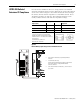
6 300 W Active Shunt Regulator
Wire the Active Shunt Module to a Drive
It is recommended to use shielded, high temperature (75 °C, 600V),
4.0 to 2.5 mm
2
(12 to 14 AWG) copper wire, or run the wire through
shielded conduit. The maximum length of each wire should be 3.05 m
(10 ft) with the shield grounded at both ends. Unshielded wiring
should be kept as short as possible.
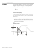
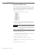
1. Locate the terminal block on your active shunt.
2. Wire the +DC Bus connection to the positive (+) bus connection
of the drive, and the -DC Bus connection to the negative (-) bus
connection of the drive.
3. Wire the AC Line Detect to the respective terminals (L1, L2/N) of
the drive or its ac power source.
The shunt module will actively sense when ac power is lost to the
drive and after 0.25/s, it will drop the dc bus.
4. Wire the Chassis ground to earth ground.
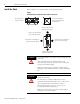
5. Tighten the terminal block screws to 1.2 Nm (11 lb-in).
6. Gently pull on each wire to make sure it does not release from its
terminal.
7. Reinsert and tighten any loose wires.
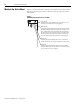
IMPORTANT
The dc bus connections should only be used to
connect a single drive to the active shunt module.
Contact your Allen-Bradley representative for further
assistance if your application requires additional dc
power connections.