
Manual

Publication 2090-IN002B-EN-P — February 2006
4 300 W Active Shunt Regulator
Install the Shunt
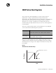
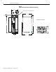
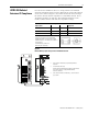
Refer to Figure 4 for shunt module spacing requirements.
Figure 4
Shunt Module Spacing Requirements within an Enclosure
A
lle
n
B
ra
d
le
y
U
l
t
r
a
S
e
r
i
e
s
Adjust
Overtemp
DC Bus
Active
Active Shunt
A
lle
n
B
ra
d
le
y
U
l
t
r
a
S
e
r
i
e
s
Adjust
Overtemp
DC Bus
Active
Active Shunt
Do not mount shunt
module on its side.
Do not mount temperature
sensitive components above
the shunt module.
1.25 mm (0.5 in.) min clearance on
each side of the shunt module.
5 mm (2 in.) min clearance
above the shunt module.
2.5 mm (1.0 in.) min clearance
in front of the shunt module.
5 mm (2 in.) min clearance
below the shunt module.
1.25 mm (0.5 in.) min clearance on
each side of the shunt module.
ATTENTION
The shunt module can release a large amount of heat
over time.
Any materials above the shunt module or its
enclosure may need the protection of a metal plate
to keep from deteriorating.
Failure to observe this precaution could result in
damage to surrounding materials, possibly leading to
fire.
ATTENTION
The shunt module can release a large amount of heat
inside an enclosure.
Be sure there is enough ventilation so as the
maximum ambient temperature of 40 °C (104 °F) is
not exceeded. Power performance must be
decreased 5.5 W for every 1.0 °C (3.1 °F) of
increasing ambient temperature.
Failure to observe this precaution could result in
damage to the shunt module.