
Manual

Publication 2090-IN002B-EN-P — February 2006
300 W Active Shunt Regulator 3
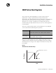
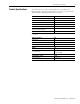
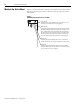
If the required average shunt power over the machine cycle is ≤ 300 W
and the cycle time is ≤ 300 seconds, the active shunt can handle the
application. Figure 3 illustrates the capability of an active shunt at
40 ºC (104 ºF) ambient temperature. The different lines represent
different cycle times (rates). The x-axis is the shunt power during the
shunt time and the y-axis is the maximum shunt time for that power
and cycle time. For example, the bottom line is a 5 second cycle time
(meaning the shunt pulse comes every 5 seconds) and it intersects the
800 W pulse for 2 seconds every five seconds in a 40 ºC (104 ºF) or
less environment. This means that the shunt can handle an 800 W
pulse lasting for two seconds, every 5 seconds if the ambient
temperature is not above 40 ºC (104 ºF).
Figure 3
Active Shunt Module Thermal Capacity
IMPORTANT
The limiting factor on how much average power can
be dissipated is temperature. The shunt power
capability increases approximately 5.5 W for every
1.0 ºC drop in ambient temperature (3.1 W/ ºF).
Increasing the air flow across the heat sink can
increase the continuous shunt capability significantly,
although obstructing air flow can decrease it
significantly.
Shunt Cycle Times
One-Shot
5 Minute Cycle
2 Minute Cycle
30 Second Cycle
5 Second Cycle
Shunt Power (watts)
Shunt Time (seconds)
(showing seconds)
Pulse Time versus Pulse Power
Different Cycle Times for the Active Shunt
Lower left of lines is safe, upper right is unsafe.
Graph assumes 40 ºC (104 ºF) ambient.