
Installation Instructions Owner manual


Rockwell Automation Publication 2090-IN007D-EN-P - August 2010 PN-78228
Supersedes Publication 2090-IN007C-EN-P - January 2007 Copyright © 2010 Rockwell Automation, Inc. All rights reserved. Printed in the U.S.A.
Allen-Bradley, Rockwell Automation, Rockwell Software, and Ultra3000 are trademarks of Rockwell Automation, Inc.
Trademarks not belonging to Rockwell Automation are property of their respective companies.
Rockwell Otomasyon Ticaret A.Ş., Kar Plaza İş Merkezi E Blok Kat:6 34752 İçerenköy, İstanbul, Tel: +90 (216) 5698400
Catalog Number 2090-U3BB-DM12
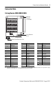
Connector
Pin
Signal Connector
Pin
Signal
SERCOS Non-SERCOS SERCOS Non-SERCOS
CN1-3 AUXPWR
(1)
(1) The 5.2V DC auxiliary power source is connected to the AUXPWR (positive) and AUXCOM (negative) terminals. Do not
ground the supply elsewhere in the system, as AUXCOM is connected to the drive chassis ground.
AUXPWR
(1)
CN1-37 OTRAV+ INPUT7
CN1-2 AUXCOM
(1)
AUXCOM
(1)
CN1-38 OTRAV– INPUT8
CN1-31 ENABLE INPUT1 CN1-27 I/OCOM I/OCOM
CN1-32 HOME INPUT2 CN1-43 BRAKE+ RELAY+
CN1-33 REG1 INPUT3 CN1-44 BRAKE– RELAY–
CN1-34 REG2 INPUT4 SHIELD SHIELD SHIELD
CN1-3
CN1-2
CN1-31
CN1-32
CN1-33
CN1-34
CN1-37
CN1-38
CN1-27
CN1-43
CN1-44
SHIELD
5V AUX
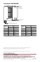
Mounting
Screw (2)
2 x 4-40 UNC
Cover Alignment
Pin (2)
Cable Shield Termination Pad