
Installation Instructions Owner manual


Control Interface Breakout Boards 3
Rockwell Automation Publication 2090-IN007D-EN-P - August 2010
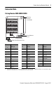
Connector Data
Catalog Number 2090-U3BB2-DM44
Terminal Signal Terminal Signal Terminal Signal
1 EPWR_5V 20 IMOUT+ 35 INPUT5
X–
(1)
(1) The 5.2V DC auxiliary power source is connected to the X+ (positive) and X– (negative) terminals. Do not ground the supply
elsewhere in the system, as X– is connected to the drive chassis ground.
AUX_COM 21 IMOUT– 36 INPUT6
X+
(1)
5V_AUX_PWR 22 ACOM 37 INPUT7
4 AX+ 23 AOUT 38 INPUT8
5 AX– 24 ILIMIT 39 OUTPUT1
6 BX+ 25 CMND+ 40 OUTPUT2
7 BX– 26 CMND– 41 OUTPUT3
8 IX+ 27 IOCOM 42 OUTPUT4
9 IX– 29 IOPWR 43 RELAY+
16 AMOUT+ 31 INPUT1 44 RELAY–
17 AMOUT– 32 INPUT2 SHIELD
18 BMOUT+ 33 INPUT3 SHIELD
19 BMOUT– 34 INPUT4
1X-X+456789
16 17 18 19 20 21 22 23 24
25 26 27 29 31 32 33 34 35
36 37 38 39 40 41 42 43 44
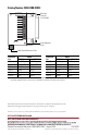
Mounting
Screw (2)
2 x 4-40 UNC
Cover Alignment
Pin (2)
Shield Terminals
Cable Shield Termination Pad