
User guide

Standard Power Cables with SpeedTec DIN Connector Type 923 5
Publication 2090-IN022A-EN-P - September 2010
2. Keep cable bends within the bend radius specified on page
7.
Never bend a cable tighter than the specified bend radius. Refer to Specifications
for the
correct value.
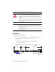
3. When installing the cable observe these restrictions:
• The bend zone is the area where the cable can be bent to its specified bend radius.
• The installation areas require strain relief to minimize cable flexing, and to reduce
the possibility of cable fatigue where the cable connects to other components.
4. Identify each connection on a cable by attaching a label around the outer insulation of
each wire adjacent to the drive connection.
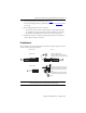
O-ring Removal
The type of plug on the connecting cable determines whether an O-ring is required on the motor
connector or the extension cable receptacle.
IMPORTANT
The O-ring dampens the effects of vibration at the connection.
This creates a more secure connection with the threaded plug.
SpeedTec Plug Remove the O-ring from an
extension cable receptacle (shown) or
a motor connector that is SpeedTec ready.
With This Plug Do This
Threaded Plug
For motors with a SpeedTec connector:
An O-ring may be installed on SpeedTec
ready motor connectors, and extension
cables.
Verify the O-ring is installed only when
mating with a threaded (non-SpeedTec)
plug.