
Instruction Manual

4 Continuous-flex Power and Brake Extension Cable with SpeedTec Connector
Publication 2090-IN028B-EN-P - January 2011
Install Cables
Follow these steps when installing a cable.
1. Provide the recommended installation areas, and the correct offset from features, before
beginning any cable bend.
Features include these areas on the cable:
• Connectors
• Transitions from exposed wire to insulation (for example, flying leads)
• Exposed cable ground shields
The offset from these areas should be greater than or equal to (>
1x) the cable diameter.
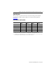
2. Keep cable bends within the bend radius listed in the Specifications
on page 7.
General guidelines for the bend radius of a cable are listed below, however, individual
cables may have additional restrictions:
• Non-flex cables have a static or one-time bend radius of 10 times (<10x) the cable
diameter.
• Continuous-flex cables have an operational bend radius of 12 times (<12x) the cable
diameter.
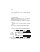
3. Observe these restrictions on the flex zone and installation areas when installing the
cable:
• The flex zone is the area in which the cable can flex many times without breakage.
• Installation areas require rigid mounting to prevent the cable from flexing where it
connects to other components.
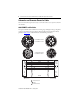
4. Identify each connection on a cable by attaching a label around the outer insulation of
each wire adjacent to the drive connection.
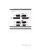
Flex Area
Dynamic and continuous
flexing permitted to the
operational bend radius.
2090-CPBM7E7-xxAFxx Shown
Installation Area
300 mm (12 in.) approx.
Bend Radius
Refer to Specifications
on page 7
for the specific value.
Installation Area
300 mm (12 in.) approx.