
Owner's manual
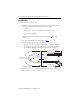
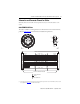
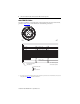
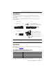
Table Of Contents
Standard Feedback Cables with SpeedTec DIN Connector Type 623 5
Publication 2090-IN029A-EN-P - September 2010
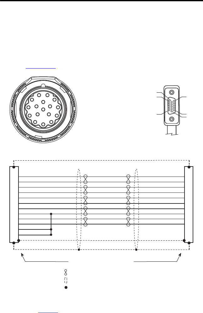
Schematics and Connector Pinouts for Cables
Schematics show wire colors and connector pinouts necessary to connect the cable to a servo
system.
2090-CFBM7DD-CEAAxx
This cable is available in several lengths. Refer to the Kinetix Motion Control Selection Guide,
publication GMC-SG001
, for this information and additional specifications.
(1) Wire gauge and connector keying varies based on motor and power requirements. Refer to Kinetix Motion Control Selection
Guide, publication GMC-SG001
, for additional information.
1
2
3
4
5
10
14
6
7
11
22 AWG Black
22 AWG White/Black
22 AWG Red
22 AWG White/Red
22 AWG Green
22 AWG White/Green
22 AWG Grey
22 AWG White/Grey
22 AWG Orange
22 AWG White/Orange
36 AWG Shield
1
2
3
4
5
6
9
10
11
13
14
12
SIN+/AM+
SIN-/AM-
COS+/BM+
COS-/BM-
DATA+/IM+/R1
DATA-/IM-/R2
EPWR 5V
ECOM
EPWR 9V
TS+
TS-
ECOM
SIN+/AM+
SIN-/AM-
COS+/BM+
COS-/BM-
DATA+/IM+/R1
DATA-/IM-/R2
EPWR 5V
ECOM
EPWR 9V
TS+
1
2
3
4
5
16
1514
13
12
11
10
9
8
7
6
17
1
5
10
15
11
6
Twisted Wire Pair
Wire Connection
Shield
Connector Backshell Shielded
To
Motor
To
Drive