
Owner's manual
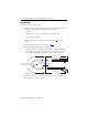
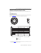
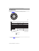
Table Of Contents
4 Standard Feedback Cables with SpeedTec DIN Connector Type 623
Publication 2090-IN029A-EN-P - September 2010
Install Cables
Follow these steps when installing a cable.
1. Identify the recommended installation areas and the correct offset from features before
beginning any cable bend. Features include these areas on the cable:
• Connectors
• Transitions from exposed wire to insulation (for example, flying leads)
• Exposed cable ground shields
The offset from these features should be greater than or equal to (>
1x) the cable
diameter.
2. Keep cable bends within the bend radius specified on page
7.
3. When installing the cable observe these restrictions:
• The bend zone is the area in which the cable can bent to its specified bend radius.
• The installation areas require strain relief to minimize cable flexing, and to reduce
the possibility of cable fatigue where the cable connects to other components.
4. Identify each connection on a cable by attaching a label around the outer insulation of
each wire adjacent to the drive connection.
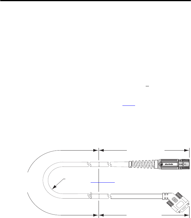
Limited Bend Zone
Flex Restrictions Apply
2090-CFBM7E7-CDAFxx shown
Installation Area
300 mm (12 in.) approx.
Bend Radius
Refer to Specifications
for value.
Installation Area
300 mm (12 in.) approx.