Installation Instructions Micro800 Remote LCD Catalog Number 2080-REMLCD http://rockwellautomation.com/literature FR IT DE ES Cette publication est disponible en français sous forme électronique (fichier PDF). Pour la télécharger, rendez-vous sur la page Internet indiquée ci-dessus. Questa pubblicazione è disponibile in Italiano in formato PDF. Per scaricarla collegarsi al sito Web indicato sopra. Diese Publikation ist als PDF auf Deutsch verfügbar.
Micro800 Remote LCD Important User Information Solid state equipment has operational characteristics differing from those of electromechanical equipment. Safety Guidelines for the Application, Installation and Maintenance of Solid State Controls (Publication SGI-1.1 available from your local Rockwell Automation sales office or online at http://rockwellautomation.com/literature) describes some important differences between solid state equipment and hard-wired electromechanical devices.
Micro800 Remote LCD 3 Environment and Enclosure ATTENTION: This equipment is intended for use in a Pollution Degree 2 industrial environment, in overvoltage Category II applications (as defined in IEC 60664-1), at altitudes up to 2000 m (6562 ft) without derating. This equipment is not intended for use in residential environments and may not provide adequate protection to radio communication services in such environments. This equipment is supplied as open-type equipment.
Micro800 Remote LCD North American Hazardous Location Approval The following modules are North American Hazardous Location approved: 2080-REMLCD. The following information applies when operating this equipment in hazardous locations: Informations sur l’utilisation de cet équipement en environnements dangereux: Products marked "CL I, DIV 2, GP A, B, C, D" are suitable for use in Class I Division 2 Groups A, B, C, D, Hazardous Locations and nonhazardous locations only.
Micro800 Remote LCD 5 • Make sure all connectors are securely tightened to properly seal the connections against leaks and maintain IP enclosure type requirements. • The USB port is intended for temporary local programming purposes only and not intended for permanent connection. • The USB cable is not to exceed 3.0 m (9.84 ft) and must not contain hubs. • The RS232 and Power cables are not to exceed 3.0 m (9.84 ft). • Do not place the module in direct sunlight.
Micro800 Remote LCD Additional Resources Resource Description Micro820 20-point Programmable Controllers User Manual, publication 2080-UM005 Micro800 Plug-in Modules and Accessories User Manual, publication 2080-UM004 Micro820 Programmable Controllers Installation Instructions, publication 2080-IN009 Micro800 AC Power Supply Installation Instructions, publication 2080-IN001 Industrial Automation Wiring and Grounding Guidelines, publication 1770-4.
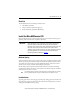
Micro800 Remote LCD 7 Overview The Micro800™ Remote LCD is a simple IP65 text display interface that allows configuration of such settings as IP address on the Micro800 controller. It is an accessory to the Micro820 controller. The remote LCD can be connected to the controller through an RS232 port. It can be mounted through the front panel or on the same DIN rail as the controller.
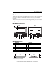
Micro800 Remote LCD ATTENTION: The length of RS232 and 24V DC power cable connection to the 2080-REMLCD module must not exceed 3 m (9.84 ft.). Micro820 controller Power supply Micro800 REMLCD F1 F4 F2 F3 ESC F5 F6 OK MENU 46258 RS232 and 24V DC power cable connections must not exceed 3 m. Module Dimensions b c a F1 F2 F3 ESC F4 F5 F6 OK MENU Catalog Number Height (a) Width (b) Depth (c) 2080-REMLCD 97 mm (3.82 in.) 130 (5.11 in.) 35.5 (1.40 in.
Micro800 Remote LCD 9 Parts List The Micro800 Remote LCD module ships with these items: • Allen-Bradley sticker label • Clamp accessories for panel mounting (4 pcs) • Product Information (publication 2080-PC002) Install the Micro800 Remote LCD Before installing the Remote LCD through the front panel, review minimum clearances, panel guidelines, panel cutout dimensions, and product dimensions.
Micro800 Remote LCD Panel Cutout Dimensions You can print the panel cutout template that comes at the end of this installation instructions. Panel cutout dimensions are provided in the next table. Catalog Number Height, Approx., mm (inches) Width, Approx., mm (inches) 2080-REMLCD 88.5 ± 0.5 (3.48 ± 0.02) 121.5 ± 0.5 (4.78 ± 0.02) ATTENTION: Disconnect all electrical power from the panel before making the panel cutout. • Make sure the area around the panel cutout is clear.
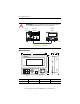
Micro800 Remote LCD 11 Mount the Module in a Panel The Micro800 Remote LCD installs easily on the front panel. Use the clamp accessories shipped with your module to mount it. 130 (5.11) 120.7 (4.75) 130 (3.81) 87.7 (3.45) Measurements are in millimeters (inches) Panel thickness: 1…5 35 (max) mounting screw clamps NOTE: The REMLCD module can only be installed through the front panel.
Micro800 Remote LCD Follow these steps to mount the remote LCD through the front panel. 1. Make sure the sealing gasket is properly positioned on the module. This gasket forms a compression type seal. Do not use sealing compounds. 2. Place the module in the panel cutout. IMPORTANT The module temperature must be greater than 0 °C (32 °F) during panel installation. The module is shipped with the Allen-Bradley logo sticker (36.70 x 4.70 mm). You can customize this space with your product logo.
Micro800 Remote LCD IMPORTANT 13 Do not push on the LCD display when pushing the terminal into the panel or you may damage the display. ATTENTION: Follow the instructions to provide a proper seal and to prevent potential damage to the device. Allen-Bradley assumes no responsibility for water or chemical damage to the terminal or other equipment within the enclosure because of improper installation. Mount the Module on a DIN Rail The module can be mounted using the following DIN rails: 35 x 7.
Micro800 Remote LCD Connect Power The Micro800 Remote LCD connects to a 24V DC power source. See the Specifications on page 18 for the module power ratings. The internal, nonisolated power supply is protected against reverse polarity of the DC+ and DC connections. ATTENTION: Connecting DC+ or DC- source to the functional earth terminal may damage the device.
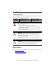
Micro800 Remote LCD 15 2. Secure the 24V DC power wires. 3. Secure the functional earth ground wire to the functional earth ground terminal screw on the terminal block. 4. Apply 24V DC power to the terminal. Ground the Module The optimum method for grounding electronic equipment is to ground it separately from other high-power systems, and to ground more than one unit of electronic equipment with a single-point ground.
Micro800 Remote LCD RS232 Port The RS232 port interface allows the Micro800 Remote LCD module to communicate with the Micro800 controller. Belden #9608 (or equivalent) shielded, three conductor cable, designed for RS232 applications, must be used. Below are pin assignments for the RS232 port terminal block on the REMLCD.
Micro800 Remote LCD WARNING: The USB port is intended for temporary local programming purposes only and not intended for permanent connection. If you connect or disconnect the USB cable with power applied to this module or any device on the USB network, an electrical arc can occur. This could cause an explosion in hazardous location installations. Be sure that power is removed or the area is nonhazardous before proceeding. ATTENTION: Do not use the USB port in hazardous locations.
Micro800 Remote LCD Specifications General Specifications Attribute Value Dimensions, HxWxD 97 x 130 x 35.5 mm (3.82 x 5.12 x 1.40 in.) Display type 192 x 64 pixel monochrome Display size 48 x 106.5 mm (1.89 x 4.19 in.
Micro800 Remote LCD Environmental Specifications Attribute Value Temperature, operating IEC 60068-2-1 (Test Ad, Operating Cold), IEC 60068-2-2 (Test Bd, Operating Dry Heat), IEC 60068-2-14 (Test Nb, Operating Thermal Shock): -20…50 °C (-4…122 °F) Temperature, surrounding air, max 50 °C (122 °F) Temperature, nonoperating IEC 60068-2-1 (Test Ab, Unpackaged Nonoperating Cold), IEC 60068-2-2 (Test Bb, Unpackaged Nonoperating Dry Heat), IEC 60068-2-14 (Test Na, Unpackaged Nonoperating Thermal Shock): -40
Certifications Certification (when product is marked)(1) Value c-UL-us UL Listed Industrial Control Equipment, certified for US and Canada. See UL File E322657. UL Listed for Class I, Division 2 Group A,B,C,D Hazardous Locations, certified for U.S. and Canada. See UL File E334470. CE European Union 2004/108/EC EMC Directive, compliant with: EN 61326-1; Meas./Control/Lab.
88.5 mm [3.48 in] Micro800 Remote LCD Cutout Template 121.5 mm [4.
Micro800 Remote LCD Notes: Rockwell Automation Publication 2080-IN010A-EN-P – December 2013
Micro800 Remote LCD Notes: Rockwell Automation Publication 2080-IN010A-EN-P – December 2013 23
Rockwell Automation Support Rockwell Automation provides technical information on the Web to assist you in using its products. At http://support.rockwellautomation.com, you can find technical manuals, a knowledge base of FAQs, technical and application notes, sample code and links to software service packs, and a MySupport feature that you can customize to make the best use of these tools.