
User Manual Owner manual

36 Rockwell Automation Publication 2080-UM005A-EN-E - December 2013
Chapter 4 Wire Your Controller
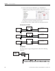
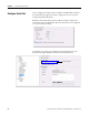
5. In Connected Components Workbench, go to Embedded I/O
configuration page. Change the Gain parameter value for Input 00 to 98.
No changes are required to the Offset parameter value.
6. Repeat the same steps to calibrate all the other analog input channels.
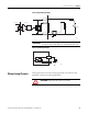
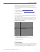
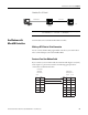
Analog Input to Transmitters
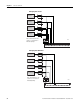
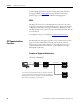
Analog Output
The analog output can support voltage function as shown in the following
illustration.
Power
Supply
+
–
2-wire Transmitter
+
–
Supply
GND
Signal
Controller
I-00, I-01, I-02 or I-03
-DC24
+
–
Controller
I-00, I-01, I-02 or I-03
-DC24
Supply
Signal
+
–
Controller
I-00, I-01, I-02 or I-03
-DC24
+
+
–
–
3-wire Transmitter
4-wire Transmitter
Power
Supply
Power
Supply
46257
Voltage
Load
+DC24 -DC24
VO-0-DC24
NU
CM0
O-00
CM1 CM2
O-01
O-03
O-02
12345678 9101112
O-04
CM3
O-06
O-05
13 14 15 16
46256