
User Manual Owner manual

Rockwell Automation Publication 2080-UM005A-EN-E - December 2013 35
Wire Your Controller Chapter 4
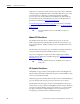
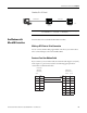
Calculate for Thermistor Resistance
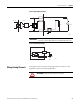
While connecting Analog input to thermistor as shown in previous diagram,
calculate input voltage using the following equation:
Where:
Vi = Voltage input (±5% without calibration; ±2% with calibration)
Ri = Resistance input (14.14 KΩ ±2%)
Rt = Thermistor resistance (10 KΩ Thermistor is recommended)
Vref = 10V ±0.5V
To calculate for thermistor resistance, use the following equation.
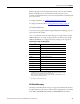
Calibrate Thermistor
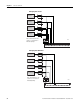
1. Connect a resistor (10 KΩ is recommended) across Vref and Analog
Input 00 of your Micro820 controller following the diagram, Analog input
to thermistors on page34. The resistor is measured as Ri using a precision
multimeter.
2. Calculate the ideal counts (C1) for resistor (Ri) following this equation:
C1 = 14.14 KΩ / (14.14 KΩ + Ri) * 4095
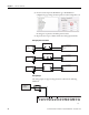
3. Read the actual counts (C2) of Analog Input 00 from Connected
Components Workbench.
4. Calculate for calibration Gain.
Gain = C1/C2
For example:
If Ri is measured as 10.00 KΩ, then
C1 = 14.14 / (14.14 + 10.00) * 4095 = 2399 counts;
C2 is read from Connected Components Workbench as 2440; so
Gain = 2399/2440 = 98% .
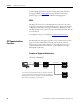
IMPORTANT
Micro820 controllers support 10 KΩ type thermistors.
In order to get the best results, the system must be calibrated.
Vi =
Ri + Rt
Ri
*
Vref
Rt=
Vi
Vi Vref - Vi Ri