
User Manual Owner manual


Rockwell Automation Publication 2080-UM005A-EN-E - December 2013 25
Chapter
4
Wire Your Controller
This chapter provides information on the Micro820 controller wiring
requirements. It includes the following sections:
Wiring Requirements and
Recommendation
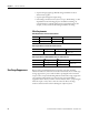
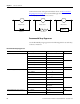
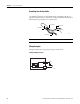
• Allow for at least 50 mm (2 in.) between I/O wiring ducts or terminal
strips and the controller.
• Route incoming power to the controller by a path separate from the device
wiring. Where paths must cross, their intersection should be
perpendicular.
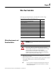
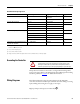
Topic Page
Wiring Requirements and Recommendation 25
Use Surge Suppressors 26
Recommended Surge Suppressors 28
Grounding the Controller 29
Wiring Diagrams 29
Controller I/O Wiring 30
Minimize Electrical Noise 31
Analog Channel Wiring Guidelines 31
Minimize Electrical Noise on Analog Channels 31
Grounding Your Analog Cable 32
Wiring Examples 32
WARNING: Before you install and wire any device, disconnect power to
the controller system.
WARNING: Calculate the maximum possible current in each power and
common wire. Observe all electrical codes dictating the maximum
current allowable for each wire size. Current above the maximum ratings
may cause wiring to overheat, which can cause damage.
United States Only: If the controller is installed within a potentially
hazardous environment, all wiring must comply with the requirements
stated in the National Electrical Code 501-10 (b).
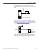
TIP
Do not run signal or communications wiring and power wiring in the
same conduit. Wires with different signal characteristics should be
routed by separate paths.