User Manual Micro820 Programmable Controllers Catalog Numbers 2080-LC20-20QWB, 2080-LC20-20QBB, 2080-LC20-20AWB, 2080-LC20-20QWBR, 2080LC20-20QBBR, 2080-LC20-20AWBR
Important User Information Solid-state equipment has operational characteristics differing from those of electromechanical equipment. Safety Guidelines for the Application, Installation and Maintenance of Solid State Controls (publication SGI-1.1 available from your local Rockwell Automation sales office or online at http://www.rockwellautomation.com/literature/) describes some important differences between solid-state equipment and hard-wired electromechanical devices.
Preface Read this preface to familiarize yourself with the rest of the manual. It provides information concerning: • • • • who should use this manual the purpose of this manual related documentation supporting information for Micro800™ Who Should Use this Manual Use this manual if you are responsible for designing, installing, programming, or troubleshooting control systems that use Micro800 controllers. Purpose of this Manual This manual is a reference guide for Micro820 controllers.
Preface Resource Description Micro800 Non-isolated Thermocouple Plug-in Module Wiring Diagrams 2080-WD006 Information on mounting and wiring the Micro800 Non-isolated Thermocouple Plug-in Module. Micro800 Memory Backup and High Accuracy RTC Plug-In Module Wiring Diagrams 2080-WD007 Information on mounting and wiring the Micro800 Memory Backup and High Accuracy RTC Plug-In Module.
Table of Contents Preface Who Should Use this Manual . . . . . . . . . . . . . . . . . . . . . . . . . . . . . . . . . . . . . . . 7 Purpose of this Manual . . . . . . . . . . . . . . . . . . . . . . . . . . . . . . . . . . . . . . . . . . . . . 7 Additional Resources . . . . . . . . . . . . . . . . . . . . . . . . . . . . . . . . . . . . . . . . . . . . . . . 7 Chapter 1 Hardware Overview Hardware Features . . . . . . . . . . . . . . . . . . . . . . . . . . . . . . . . . . . . . . . . . . . . . . . . .
Table of Contents Connect the Controller to an EtherNet/IP Network . . . . . . . . . . . . . . . . 21 Install the microSD Card . . . . . . . . . . . . . . . . . . . . . . . . . . . . . . . . . . . . . . . . . 22 Install the 2080-REMLCD Module. . . . . . . . . . . . . . . . . . . . . . . . . . . . . . . . 23 Chapter 4 Wire Your Controller Wiring Requirements and Recommendation . . . . . . . . . . . . . . . . . . . . . . . Wire Requirements . . . . . . . . . . . . . . . . . . . . . . . . . . . . . . . . .
Chapter 1 Power Up and First Scan. . . . . . . . . . . . . . . . . . . . . . . . . . . . . . . . . . . . . . . . . . Variable Retention . . . . . . . . . . . . . . . . . . . . . . . . . . . . . . . . . . . . . . . . . . . Memory Allocation . . . . . . . . . . . . . . . . . . . . . . . . . . . . . . . . . . . . . . . . . . . . . . Guidelines and Limitations for Advanced Users . . . . . . . . . . . . . . . . . . . . 53 54 54 54 Chapter 7 Controller Security Exclusive Access. . . . . . . . . . . . . . . .
Table of Contents Use the Recipe Feature . . . . . . . . . . . . . . . . . . . . . . . . . . . . . . . . . . . . . . . . 94 Appendix A Specifications . . . . . . . . . . . . . . . . . . . . . . . . . . . . . . . . . . . . . . . . . . . . . . . . . . . . . . . . . . . . . . . . 101 Appendix B Troubleshooting Status Indicators on the Controller . . . . . . . . . . . . . . . . . . . . . . . . . . . . . . . Normal Operation . . . . . . . . . . . . . . . . . . . . . . . . . . . . . . . . . . . . . . . . . .
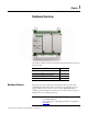
Chapter 1 Hardware Overview This chapter provides an overview of the Micro820 hardware features. It has the following topics: Hardware Features Topic Page Hardware Features 1 Embedded microSD (Micro Secure Digital) Card Slot 3 Embedded RS232/RS485 Serial Port Combo 3 Embedded Ethernet Support 4 Micro820 controllers are 20-point economical brick style controllers with embedded inputs and outputs.
Chapter 1 Hardware Overview For information on the REMLCD module, see Using the Micro800 Remote LCD on page 63. The controller also accommodates any class 2 rated 24V DC output power supply that meets minimum specifications such as the optional Micro800 power supply.
Hardware Overview Chapter 1 Inputs and Outputs Number and Types of Inputs/Outputs for Micro820 Controllers Controller Family Catalogs Micro820 Inputs Outputs 120V AC 120 / 240V AC 24V DC 2080-LC20-20QBB – – 12 2080-LC20-20QWB – – 12 2080-LC20-20AWB 8 – 2080-LC20-20QBBR – Relay Analog Out 0…10V DC Analog In 0…10V (shared with DC In) PWM Support 24V DC Source 24V DC Sink 7 – 1 4 1 7 – – 1 4 – 4 7 – – 1 4 – – 12 – 7 – 1 4 1 2080-LC20-20QWBR – – 12 7 –
Chapter 1 Hardware Overview RS232/RS485 Serial Port Pin Definition D+ 1 G 2 Tx 3 4 D- 5 Rx Pin Definition RS485 Example RS232 Example 1 RS485+ RS485+ (not used) 2 RS485- RS485- (not used) 3 GND GND GND 4 RS232 input (receiver) (not used) RxD 5 RS232 output (driver) (not used) TxD 6 GND GND GND 6 G The communication port (both RS232 and RS485) are non-isolated. The signal ground of the port is not isolated to the logic ground of the controller.
Hardware Overview Chapter 1 Ethernet port pin-to-pin connection 1 2 3 4 white-orange orange white-green blue 5 6 7 8 white-blue green white-brown brown 1 2 3 4 white-orange orange white-green blue 5 6 7 8 white-blue green white-brown brown 46223 See Troubleshooting on page 111 for descriptions of ENET status indicator.
Chapter 1 Hardware Overview Notes: 6 Rockwell Automation Publication 2080-UM005A-EN-E - December 2013
Chapter 2 About Your Controller Programming Software for Micro800 Controllers Connected Components Workbench is a set of collaborative tools supporting Micro800 controllers. It is based on Rockwell Automation and Microsoft Visual Studio technology and offers controller programming, device configuration and integration with HMI editor. Use this software to program your controllers, configure your devices and design your operator interface applications.
Chapter 2 About Your Controller EMC Directive This product is tested to meet Council Directive 2004/108/EC Electromagnetic Compatibility (EMC) and the following standards, in whole or in part, documented in a technical construction file: • EN 61131-2; Programmable Controllers (Clause 8, Zone A & B) • EN 61131-2; Programmable Controllers (Clause 11) • EN 61000-6-4 EMC - Part 6-4: Generic Standards - Emission Standard for Industrial Environments • EN 61000-6-2 EMC - Part 6-2: Generic Standards - Immunity fo
About Your Controller Chapter 2 WARNING: When used in a Class I, Division 2, hazardous location, this equipment must be mounted in a suitable enclosure with proper wiring method that complies with the governing electrical codes. WARNING: If you connect or disconnect the serial cable with power applied to this module or the serial device on the other end of the cable, an electrical arc can occur. This could cause an explosion in hazardous location installations.
Chapter 2 About Your Controller Environment and Enclosure This equipment is intended for use in a Pollution Degree 2 industrial environment, in overvoltage Category II applications (as defined in IEC 60664-1), at altitudes up to 2000 m (6562 ft) without derating. This equipment is considered Group 1, Class A industrial equipment according to IEC/CISPR 11.
About Your Controller Chapter 2 of your equipment, is of primary importance. We recommend reviewing the following safety considerations. North American Hazardous Location Approval The following information applies when operating this equipment in hazardous locations: Informations sur l’utilisation de cet équipement en environnements dangereux: Products marked "CL I, DIV 2, GP A, B, C, D" are suitable for use in Class I Division 2 Groups A, B, C, D, Hazardous Locations and nonhazardous locations only.
Chapter 2 About Your Controller Safety Circuits WARNING: Explosion Hazard Do not connect or disconnect connectors while circuit is live. Circuits installed on the machine for safety reasons, like overtravel limit switches, stop push buttons, and interlocks, should always be hard-wired directly to the master control relay. These devices must be wired in series so that when any one device opens, the master control relay is de-energized, thereby removing power to the machine.
About Your Controller Chapter 2 Isolation Transformers You may want to use an isolation transformer in the AC line to the controller. This type of transformer provides isolation from your power distribution system to reduce the electrical noise that enters the controller and is often used as a stepdown transformer to reduce line voltage. Any transformer used with the controller must have a sufficient power rating for its load. The power rating is expressed in volt-amperes (VA).
Chapter 2 About Your Controller Input States on Power Down The power supply hold-up time as described above is generally longer than the turn-on and turn-off times of the inputs. Because of this, the input state change from “On” to “Off ” that occurs when power is removed may be recorded by the processor before the power supply shuts down the system. Understanding this concept is important. The user program should be written to take this effect into account.
About Your Controller Chapter 2 WARNING: Never alter these circuits to defeat their function since serious injury and/or machine damage could result. TIP If you are using an external DC power supply, interrupt the DC output side rather than the AC line side of the supply to avoid the additional delay of power supply turn-off. The AC line of the DC output power supply should be fused. Connect a set of master control relays in series with the DC power supplying the input and output circuits.
Chapter 2 About Your Controller • Install emergency-stop switches and the master control relay in your system. Make certain that relay contacts have a sufficient rating for your application. Emergency-stop switches must be easy to reach. • In the following illustration, input and output circuits are shown with MCR protection. However, in most applications, only output circuits require MCR protection. The following illustrations show the Master Control Relay wired in a grounded system.
About Your Controller Chapter 2 Schematic (Using IEC Symbols) L1 L2 230V AC Disconnect Fuse MCR 230V AC I/O Circuits Isolation Transformer X1 115V AC X2 or 230V AC Operation of either of these contacts will remove power from the external I/O circuits, stopping machine motion. Emergency-Stop Push Button Overtravel Limit Switch Fuse Stop Start Master Control Relay (MCR) Cat. No. 700-PK400A1 Suppressor Cat. No. 700-N24 MCR Suppr.
Chapter 2 About Your Controller Schematic (Using ANSI/CSA Symbols) L1 230V AC L2 Disconnect Fuse Isolation Transformer X1 115V AC or 230V AC Fuse X2 Operation of either of these contacts will remove power from the external I/O circuits, stopping machine motion. Emergency-Stop Push Button Overtravel Limit Switch MCR Master Control Relay (MCR) Cat. No. 700-PK400A1 Suppressor Cat. No. 700-N24 Start Stop 230V AC Output Circuits MCR Suppr. MCR MCR DC Power Supply. Use NEC Class 2 for UL Listing.
Chapter 3 Install Your Controller This chapter serves to guide the user on installing the controller. It includes the following topics. Controller Mounting Dimensions Topic Page Controller Mounting Dimensions 19 Connect the Controller to an EtherNet/IP Network 21 Module Spacing 20 DIN Rail Mounting 20 Panel Mounting 20 Panel Mounting Dimensions 21 Install the microSD Card 22 Install the 2080-REMLCD Module 23 Mounting dimensions do not include mounting feet or DIN rail latches.
Chapter 3 Install Your Controller Module Spacing Maintain spacing from enclosure walls, wireways, and adjacent equipment. Allow 50.8 mm (2 in.) of space on all sides. This provides ventilation and electrical isolation. If optional accessories/modules are attached to the controller, such as the power supply 2080-PS120-240VAC or expansion I/O modules, make sure that there is 50.8 mm (2 in.) of space on all sides after attaching the optional parts.
Install Your Controller Chapter 3 Panel Mounting Dimensions Micro820 20-point controllers 2080-LC20-20AWB, 2080-LC20-20QWB, 2080-LC20-20QBB 2080-LC20-20AWBR, 2080-LC20-20QWBR, 2080-LC20-20QBBR 86 mm (3.39 in.) 100 mm (3.94 in.) 46204 Connect the Controller to an EtherNet/IP Network WARNING: If you connect or disconnect the communications cable with power applied to this module or any device on the network, an electrical arc can occur. This could cause an explosion in hazardous location installations.
Chapter 3 Install Your Controller Connect the RJ-45 connector of the Ethernet cable to the Ethernet port on the controller. The port is on the bottom of the controller. 46214 Install the microSD Card 1. Insert the microSD card into the card slot. You can install the microSD card in one orientation only. The beveled corner should be at the bottom. If you feel resistance when inserting the microSD card, pull it out and change the orientation. Insert the microSD card into the slot. 46218 2.
Install Your Controller Chapter 3 3. To remove the microSD card from the slot, gently press the card until it clicks back and releases itself from the slot. Install the 2080-REMLCD Module The Micro820 controller supports the 2080-REMLCD module, a simple text display interface for configuring settings such as IP address. It can be mounted through a front panel or on the same DIN rail as the controller.
Chapter 3 Install Your Controller Notes: 24 Rockwell Automation Publication 2080-UM005A-EN-E - December 2013
Chapter 4 Wire Your Controller This chapter provides information on the Micro820 controller wiring requirements.
Chapter 4 Wire Your Controller • Separate wiring by signal type. Bundle wiring with similar electrical characteristics together. • Separate input wiring from output wiring. • Label wiring to all devices in the system. Use tape, shrink-tubing, or other dependable means for labeling purposes. In addition to labeling, use colored insulation to identify wiring based on signal characteristics. For example, you may use blue for DC wiring and red for AC wiring.
Wire Your Controller Chapter 4 The following diagram shows an output with a suppression device. We recommend that you locate the suppression device as close as possible to the load device. +DC or L1 Suppression device VAC/DC Out 0 Out 1 AC or DC outputs Out 2 Out 3 Load Out 4 Out 5 Out 6 COM DC COM or L2 If the outputs are DC, we recommend that you use an 1N4004 diode for surge suppression, as shown below. For inductive DC load devices, a diode is suitable.
Chapter 4 Wire Your Controller transient characteristic of the particular inductive device. See Recommended Surge Suppressors on page 28 for recommended suppressors. Surge Suppression for Inductive AC Load Devices Output device Output device Output device Surge suppressor RC network Varistor Recommended Surge Suppressors Use the Allen-Bradley surge suppressors in the following table for use with relays, contactors, and starters.
Wire Your Controller Chapter 4 Recommended Surge Suppressors Device Coil Voltage Suppressor Catalog Number Type(4) Bulletin 509 Motor Starter Size 6 12…120V AC 199-FSMA1(2) RC 12…120V AC 199-GSMA1(3) MOV AC coil Not Required 24…48V DC 199-FSMA9 50…120V DC 199-FSMA10 130…250V DC 199-FSMA11 6…150V AC/DC 700-N24 RC 24…48V AC/DC 199-FSMA9 MOV 50…120V AC/DC 199-FSMA10 130…250V AC/DC 199-FSMA11 6…300V DC 199-FSMZ-1 Diode 6…150V AC/DC 700-N24 RC Bulletin 700 R/RM Relay Bulleti
Chapter 4 Wire Your Controller 2080-LC20-20AWB, 2080-LC20-20QWB, 2080-LC20-20AWBR, 2080-LC20- 20QWBR Input Terminal Block +DC10 I-00 1 2 I-02 3 4 -DC24 +DC24 I-01 2 7 4 I-05 8 O-00 5 6 VO-0 9 I-04 NU 3 -DC24 6 I-03 -DC24 1 COM0 5 7 CM0 I-07 10 9 CM1 I-09 12 O-02 10 13 I-08 I-06 O-01 8 11 11 CM2 I-11 14 I-10 CM3 12 15 13 O-03 16 NU O-05 14 15 O-04 16 O-06 46212 Output Terminal Block ATTENTION: For 2080-LC20-20AWB/R catalogs, inputs 00…03 are lim
Wire Your Controller Chapter 4 Minimize Electrical Noise Because of the variety of applications and environments where controllers are installed and operating, it is impossible to ensure that all environmental noise will be removed by input filters. To help reduce the effects of environmental noise, install the Micro800 system in a properly rated (for example, NEMA) enclosure. Make sure that the Micro800 system is properly grounded.
Chapter 4 Wire Your Controller Grounding Your Analog Cable Use shielded communication cable (Belden #8761). The Belden cable has two signal wires (black and clear), one drain wire, and a foil shield. The drain wire and foil shield must be grounded at one end of the cable. Foil shield Insulation Black wire Drain wire Clear wire IMPORTANT 44531 Do not ground the drain wire and foil shield at both ends of the cable. Wiring Examples Examples of sink/source, input/output wiring are shown below.
Wire Your Controller Chapter 4 Source Output Wiring Example +V DC Logic side Fuse User side S OUT + G Load – 24V Supply D DC COM 45626 IMPORTANT For 2080-LC20-20QBB(R) discrete output 06, shielded cable is required if the output is used as PWM. Otherwise, unshielded cable can be used.
Chapter 4 Wire Your Controller Analog input to sensors Sensor 3 (V) Voltage Sensor 2 (V) Voltage Sensor 1 (V) Voltage Sensor 0 (V) Voltage Note: Terminal block to wire commons is not included in Micro800 package.
Wire Your Controller Chapter 4 Calculate for Thermistor Resistance While connecting Analog input to thermistor as shown in previous diagram, calculate input voltage using the following equation: Vi = Ri Ri + Rt * Vref Where: Vi = Voltage input (±5% without calibration; ±2% with calibration) Ri = Resistance input (14.14 KΩ ±2%) Rt = Thermistor resistance (10 KΩ Thermistor is recommended) Vref = 10V ±0.5V To calculate for thermistor resistance, use the following equation.
Chapter 4 Wire Your Controller 5. In Connected Components Workbench, go to Embedded I/O configuration page. Change the Gain parameter value for Input 00 to 98. No changes are required to the Offset parameter value. 6. Repeat the same steps to calibrate all the other analog input channels.
Chapter 5 Communication Connections Overview This chapter describes how to communicate with your control system and configure communication settings. The method you use and cabling required to connect your controller depends on what type of system you are employing. This chapter also describes how the controller establishes communication with the appropriate network.
Chapter 5 Communication Connections single master to communicate with a maximum of 247 slave devices. Micro800 controllers support Modbus RTU Master and Modbus RTU Slave protocol. For more information on configuring your Micro800 controller for Modbus protocol, refer to the Connected Components Workbench Online Help. For more information about the Modbus protocol, refer to the Modbus Protocol Specifications (available from http://www.modbus.org).
Communication Connections Chapter 5 EtherNet/IP, supported on the Micro820 controller, makes use of the standard Ethernet TCP/IP protocol. The Micro820 controller supports up to 16 simultaneous EtherNet/IP Client connections and 16 simultaneous EtherNet/IP Server connections. To configure CIP Serial, see Configure CIP Serial Driver on page 43. To configure for EtherNet/IP, see Configure Ethernet Settings on page 48.
Chapter 5 Communication Connections See Micro800 Programmable Controllers: Getting Started with CIP Client Messaging, publication 2080-QS002, for more information and sample quickstart projects to help you use the CIP Client Messaging feature. ASCII ASCII provides connection to other ASCII devices, such as bar code readers, weigh scales, serial printers, and other intelligent devices. You can use ASCII by configuring the embedded or any plug-in serial RS232 or RS485 port for the ASCII driver.
Communication Connections Chapter 5 EtherNet/IP to CIP Serial EtherNet/IP CIP Serial Micro820 Controller IMPORTANT Use Modems with Micro800 Controllers Micro820 Controller 46046 Micro800 controllers do not support more than one hop (for example, from EtherNet/IP → CIP Serial → EtherNet/IP). Serial modems can be used with the Micro820 controllers. Making a DF1 Point-to-Point Connection You can connect the Micro820 programmable controller to your serial modem.
Chapter 5 Communication Connections Configure Serial Port You can configure the Serial Port driver as CIP Serial, Modbus RTU, ASCII or choose Shutdown through the Controller Configuration tree in Connected Components Workbench software. By default, when a Micro820 controller is added to the Project Organizer in Connected Components Workbench, Remote LCD parameters are configured to overwrite serial port settings.
Communication Connections Chapter 5 When the Remote LCD configuration is unchecked, the serial port values are visible and can be edited. Configure CIP Serial Driver 1. Open your Connected Components Workbench project. On the device configuration tree, go to the Controller properties. Click Serial Port.
Chapter 5 Communication Connections 2. Select CIP Serial from the Driver field. 3. Specify a baud rate. Select a communication rate that all devices in your system support. Configure all devices in the system for the same communication rate. Default baud rate is set @ 38400 bps. 4. In most cases, parity and station address should be left at default settings. 5. Click Advanced Settings and set Advanced parameters.
Communication Connections Chapter 5 CIP Serial Driver Parameters Embedded Responses To use embedded responses, choose Enabled Unconditionally. If you want the controller to use embedded responses only when it detects embedded responses from another device, choose After One Received. If you are communicating with another Allen-Bradley device, choose Enabled Unconditionally. Embedded responses increase network traffic efficiency.
Chapter 5 Communication Connections 2. Select Modbus RTU on the Driver field. 3. Specify the following parameters: • Baud rate • Parity • Unit address • Modbus Role (Master, Slave, Auto) Modbus RTU Parameters Parameter Options Default Baud Rate 1200, 2400, 4800, 9600, 19200, 38400 19200 Parity None, Odd, Even None Modbus Role Master, Slave, Auto Master 4. Click Advanced Settings to set advanced parameters.
Communication Connections Chapter 5 Configure ASCII 1. Open your Connected Components Workbench project. On the device configuration tree, go to Controller properties. Click Serial Port. 2. Select ASCII on the Driver field. 3. Specify baud rate and parity.
Chapter 5 Communication Connections Configure Ethernet Settings 1. Open your Connected Components Workbench project (for example, Micro820). On the device configuration tree, go to Controller properties. Click Ethernet. 2. Under Ethernet, click Internet Protocol. Configure Internet Protocol (IP) settings. Specify whether to obtain the IP address automatically using DHCP or manually configure IP address, subnet mask, and gateway address.
Communication Connections Chapter 5 7. Click Save Settings to Controller if you would like to save the settings to your controller. 8. On the device configuration tree, under Ethernet, click Port Diagnostics to monitor Interface and Media counters. The counters are available and updated when the controller is in Debug mode. Ethernet Host Name Micro800 controllers implement unique host names for each controller, to be used to identify the controller on the network.
Chapter 5 Communication Connections Notes: 50 Rockwell Automation Publication 2080-UM005A-EN-E - December 2013
Chapter 6 Program Execution in Micro800 This section provides a brief overview of running or executing programs with a Micro800 controller. IMPORTANT Overview of Program Execution This section generally describes program execution in Micro800 controllers. Certain elements may not be applicable or true in certain models (for example, Micro820 does not support PTO motion control).
Chapter 6 Program Execution in Micro800 • __SYSVA_TCYCURRENT – Current cycle time • __SYSVA_TCYMAXIMUM – Maximum cycle time since last start. Execution Rules This section illustrates the execution of a program. The execution follows four main steps within a loop. The loop duration is a cycle time for a program. 1. Read inputs 1 2. Execute POUs(1)/programs 2 3 3. Write outputs 4. Housekeeping (datalog, recipe, communications) 4 1 2 (1) Program Organizational Unit.
Program Execution in Micro800 Chapter 6 marginally. The Watchdog setting defaults to 2 s and generally never needs to be changed. Periodic Execution of Programs For applications where periodic execution of programs with precise timing is required, such as for PID, it is recommended that STI (Selectable Timed Interrupt) be used to execute the program. STI provides precise time intervals.
Chapter 6 Program Execution in Micro800 Variable Retention Micro830 and Micro850 controllers retain all user-created variables after a power cycle, but the variables inside instances of instructions are cleared. For example: A user created variable called My_Timer of Time data type will be retained after a power cycle but the elapsed time (ET) within a user created timer TON instruction will be cleared.
Program Execution in Micro800 Chapter 6 • Each program/POU can use up to 64 Kb of internal address space. It is recommended that you split large programs into smaller programs to improve code readability, simplify debugging and maintenance tasks. • A User Defined Function Block (UDFB) can be executed within another UDFB, with a limit of five nested UDFBs. Avoid creating UDFBs with references to other UDFBs, as executing these UDFBs too many times may result in a compile error.
Chapter 6 Program Execution in Micro800 Notes: 56 Rockwell Automation Publication 2080-UM005A-EN-E - December 2013
Chapter 7 Controller Security Micro800 security generally has two components: • Exclusive Access which prevents simultaneous configuration of the controller by two users • Controller Password Protection which secures the Intellectual Property contained within the controller and prevents unauthorized access Exclusive Access Exclusive access is enforced on the Micro800 controller regardless of whether the controller is password-protected or not.
Chapter 7 Controller Security • Micro800 controllers with at least revision 2 firmware For users with earlier versions of the software and/or hardware, refer to the compatibility scenarios below. Connected Components Workbench revision 1 with Micro800 controller firmware revision 2 and later Connection to a Micro800 controller with firmware revision 2 using an earlier version of the Connected Components Workbench software (revision 1) is possible and connections will be successful.
Controller Security Chapter 7 Debug a Password-Protected Controller To debug a locked controller, you have to connect to the controller through the Connected Components Workbench software and provide the password before you can proceed to debug. 1. Launch the Connected Components Workbench software. 2. On the Device Toolbox, expand Catalog by clicking the + sign. 3. Select the catalog number of your controller. 4. When requested, provide the controller password. 5. Build and save your project. 6. Debug.
Chapter 7 Controller Security 7. Swap controller1 hardware with controller2 hardware. 8. Power up controller2. 9. Click Connect. 10. Select target controller2. 11. Click Download. 12. Lock controller2. See Configure Controller Password on page 128 . Back Up a Password-Protected Controller In this workflow, user application will be backed up from a Micro800 controller that is locked to a memory plug-in device. 1. On the Device Toolbox, open Discover. Click Browse Connections. 2.
Controller Security Recover from a Lost Password Chapter 7 If the controller is secured with a password and the password has been lost, then it is impossible to access the controller using the Connected Components Workbench software. To recover, the controller must be set to Program Mode using the keyswitch for Micro830 and Micro850 controllers, the 2080-LCD for Micro810 controllers, or the 2080-REMLCD for the Micro820.
Chapter 7 Controller Security Notes: 62 Rockwell Automation Publication 2080-UM005A-EN-E - December 2013
Chapter 8 Using the Micro800 Remote LCD This chapter provides a description of how you can use the Micro800 Remote LCD with the Micro820 controller. It has the following sections. Overview Topic Page Overview 63 Text Display Mode 65 USB Mode 64 Backup and Restore 71 Hardware Features, Installation, and Specifications 71 The 2080-REMLCD module serves as a simple IP65 text display that allows the configuration of such controller settings as IP address.
Chapter 8 Using the Micro800 Remote LCD Micro800 Remote LCD 3.5-inch LCD screen Keypad F1 F2 F3 ESC F4 F5 F6 OK USB port MENU RS232 serial port for connectivity to the controller The 2080-REMLCD module is IP65-rated and can be mounted through the front panel or on the same DIN rail as the Micro820 controller.
Using the Micro800 Remote LCD Chapter 8 IMPORTANT Text Display Mode Using the USB port is convenient when accessing the controller from the front of the cabinet without opening the door and when the IP address is unknown. For larger programs, it is recommended to use USB port through the Remote LCD to set the IP address and then use Ethernet to download. Ethernet is faster due to limitations of the USB to serial conversion.
Chapter 8 Using the Micro800 Remote LCD After showing the startup message, the Remote LCD will show the I/O Status screen, assuming that no LCD_REM instructions are executing. Navigate the Remote LCD In text display mode, you can make use of available navigation keys (function keys, arrow keys, ESC and OK) to navigate through the menus. F1 F4 F2 F3 ESC F5 F6 OK MENU The module has twelve keys with the following operations.
Using the Micro800 Remote LCD Chapter 8 The Main Menu shows the following screen: Mode Switch RUN 14:18WED Variables I/O Status The following structure tree takes you through the different menus available in the Remote LCD module and their general description. 2080-REMLCD Menu Structure Tree Mode Switch Set the controller to Program Mode or Run mode from this screen. Variable Monitor or set values for program-defined variables.
Chapter 8 Using the Micro800 Remote LCD Main Menu Items Menu Item Description I/O Status Shows the status of the local I/O. Mode switch Change the mode switch selection. Variables View and change the data value of a variable. Using Connected Components Workbench software, you can specify which variables in the program can be viewed and edited through the 2080-REMLCD module. See View and Edit Variable Values through the Remote LCD on page 68.
Using the Micro800 Remote LCD Chapter 8 Shows how many bytes (out of 400 allowed) have been used up User-defined Screens To create user-defined screens through Connected Components Workbench, you can program the Remote LCD module using the following function blocks. 2080-REMLCD Function Blocks Function Block Name Description LCD_REM Used to display string or numbers on the Remote LCD. KEY_READ_REM Used to read keypad input on the Remote LCD.
Chapter 8 Using the Micro800 Remote LCD LCD_REM The LCD_REM function block is used to display user strings on the REMLCD module when REMLCD is present and connected. LCD_REM Enable LCD_REM Font Sts Line 1 Line 2 Line 3 Line 4 Line 5 Line 6 Line 7 Line 8 LCD_BKLT_REM LCD_BKLT_REM Enable Color LCD_BKLT_REM Sts Mode This function block is used to configure backlight parameters on the Remote LCD module. Execution of the LCD_BKLT_REM takes precedence over current backlight settings in the Main Menu.
Using the Micro800 Remote LCD Chapter 8 KEY_READ_REM KEY_READ_REM Enable KEY_READ_REM Sts KeyData This function block can be used to read key status on the Remote LCD module when the user-defined screen is active. When user-defined screen is not active, KEY_READ_REM instruction flags an error. Note that the KEY_READ_REM instruction will always show key status as False if Push Button Key Read is disabled in Connected Components Workbench or the Remote LCD.
Chapter 8 Using the Micro800 Remote LCD Notes: 72 Rockwell Automation Publication 2080-UM005A-EN-E - December 2013
Chapter 9 Using microSD Cards This chapter provides a description of microSD card support on Micro820 controllers. Topic Page Overview 73 Project Backup and Restore 73 Backup and Restore Directory Structure 75 Powerup Settings in ConfigMeFirst.txt 76 General Configuration Rules in ConfigMeFirst.txt 77 ConfigMeFirst.
Chapter 9 Using microSD Cards triggered and configured through the Connected Components Workbench, the 2080-REMLCD module, and the ConfigMeFirst.txt file in the microSD card. Backup and restore can only occur when the controller is in PROGRAM mode. On controller powerup, restore automatically occurs if the Load Always or Load on Memory Error option has been configured in Connected Components Workbench.
Using microSD Cards Chapter 9 Backup and Restore Directory Structure When a user project is backed up, a subdirectory named Micro820/USERPRJ is created on the microSD card. The folder name takes the name of the project specified in the General Page in Connected Components Workbench, which is Micro820 by default. However, if the ConfigMeFirst.txt file specifies a different subdirectory (example: MyProject), the project is backed up to that directory. See General Configuration Rules in ConfigMeFirst.
Chapter 9 Using microSD Cards IMPORTANT The Micro800 controller reports a major fault when project backup does not succeed because the memory card size is exceeded. Powerup Settings in ConfigMeFirst.txt On powerup, the Micro820 controller reads and carries out configuration settings described in the ConfigMeFirst.txt file, as shown in the following table. ConfigMeFirst.txt Configuration Settings Setting Description [PM] Power up and switch to PROGRAM mode. [CF] Power up and attempt to clear fault.
Using microSD Cards Chapter 9 IMPORTANT Powerup Network Parameter Settings • [IPA], [SNM] and [GWA] follow the general IP configuration rules. • [IPA], when set in ConfigMeFirst.txt, should always be configured with a valid [SNM] and vice versa. • When optional [GWA] setting is used, make sure that [IPA] and [SNM] settings are also present in ConfigMeFirst.txt.
Chapter 9 Using microSD Cards • space in between IP address, subnet mask, and gateway address (for example, xxx. x xx.xxx.xxx) • [END] setting does not exist (even if there are no other settings in the configuration file). The microSD card becomes unusable until the ConfigMeFirst.txt file becomes readable or the errors are corrected. Datalog The datalogging feature allows you to capture global and local variables with timestamp from the Micro800 controller into the microSD card.
Using microSD Cards Chapter 9 Datalog Directory Structure The DATALOG folder is created under the current project directory in the microSD card. This folder is created by default unless another directory has been specified in the ConfigMeFirst.txt. See ConfigMeFirst.txt Configuration Settings on page 76. Subdirectories are also created following the controller RTC timestamp.
Chapter 9 Using microSD Cards Datalog Function (DLG) Block The datalogging function block lets a user program to write run-time global values into the datalogging file in microSD card. DLG Enable Status TSEnable ErrorID CfgId DLG Input and Output Parameters Parameter Parameter Type Data Type Description Enable INPUT BOOL Datalogging write function enable. On rising edge (that is, Enable value is triggered from low to high), the function block executes.
Using microSD Cards Chapter 9 DLG Function Block Errors Status Code Name Description 7 DLG_ERR_CFG_FORMAT Datalog configuration file format is wrong. 8 DLG_ERR_RTC Real time clock is invalid. 9 DLG_ERR_UNKNOWN Unspecified error has occurred. IMPORTANT File access error will be returned during DLG function block execution when card is full.
Chapter 9 Using microSD Cards IMPORTANT Datalog Function Block Execution • There are three possible states for the Datalog function block: Idle, • • • • • • • Busy and Complete (which includes Complete with Succeed and Complete with Error). For one Datalog function block execution, the typical status starts from Idle, then Busy and finishes with Complete. To trigger another function block execution, the status needs to go back to Idle first.
Using microSD Cards Chapter 9 Supported Data Types for Datalog and Recipe Function Blocks Data Type Description Example format in output datalog file REAL 32-bit floating point value -3.40282347E+38, +3.40282347E+38 LREAL 64-bit floating point value -1.7976931348623157E+308, +1.
Chapter 9 Using microSD Cards Recipe Directory Structure On first execution of RCP, it creates the RECIPE folder under the current project directory on the microSD card. It also creates 10 subdirectories for each recipe set with a name following the CfgID input value (1…10) . If the CfgID value is 1, then the subfolder Rcp_Id01 is created.
Using microSD Cards Chapter 9 RCP Input and Output Parameters Parameter Parameter Type Data Type Description Enable INPUT BOOL Recipe read/write function enable. If Rising Edge (Enable is triggered from "low" to "high"), starts recipe function block and the precondition is that last operation is completed. RWFlag INPUT BOOL TRUE: Recipe write data variables to recipe files into the microSD card.
Chapter 9 Using microSD Cards RCP Function Block Errors Error ID Error name Description 12 RCP_ERR_DATAFILE_ABSENT Recipe data file is absent. 13 RCP_ERR_DATAFILE_FORMAT Recipe data file contents are wrong. 14 RCP_ERR_DATAFILE_SIZE Recipe data file size is too big (>4K). IMPORTANT File access error will be returned during RCP function block execution when card is full.
Using microSD Cards Chapter 9 IMPORTANT RCP Function Block Execution • There are three possible states for Recipe function block: Idle, Busy, Complete (Complete with Succeed and Complete with Error) • For one Recipe function block execution, the typical status starts from • • • • • • • Quickstart Projects for Datalog and Recipe Function Blocks Idle then Busy and finishes with Complete. To trigger another function block execution, the status needs to go back to Idle first.
Chapter 9 Using microSD Cards Use the Datalog Feature Configure datalog Create datalog ladder program Build and download Execute DLG function block Upload datalog file Configure datalog 1. In Connected Components Workbench, go to the Properties pane to configure your datalog. 2. Select Datalog. Click Add Dataset to add a dataset. Note that each dataset will be stored in the same file. You can add up to 10 datasets per configuration. 3. Click Add Variable to add variables to the dataset.
Using microSD Cards Chapter 9 Create datalog ladder program 1. Launch Connected Components Workbench. Create a user program for your Micro820 controller. 2. Right-click Programs. Select Add New LD: Ladder Diagram. Name the Program (for example, Prog1). 3. From the Toolbox, double-click Direct Contact to add it to the rung. 4. From the Toolbox, double-click Block to add it to the rung.
Chapter 9 Using microSD Cards 5. On the Block Selector window that appears, type DLG to filter the DLG function block from the list of available function blocks. Click OK. 6. Create the following local variables for your project.
Using microSD Cards Chapter 9 7. Assign the variables to the DLG input and output parameters as follows: Note: For CfgID input parameter, you can choose a predefined variable by choosing from the Defined Words in Connected Components Workbench. To do so, click the CfgID input box. From the Variable Selector window that appears, click the Defined Words tab and choose from the list of defined words (for example, DSET1 which corresponds to DSET1 in your recipe configuration). See the following screenshot.
Chapter 9 Using microSD Cards Build and download After configuring datalog properties, build the program and download to the controller. Execute DLG function block Execute the DLG function block. Notice the Status output go from 0 (Idle) to 1 (Enable), and 2 (Succeed). Upload datalog file You can retrieve datalog files from the microSD card using a card reader or by uploading the datalogs through Connected Components Workbench. 1.
Using microSD Cards Chapter 9 IMPORTANT The Manage button is not available in DEBUG mode. You need to stop DEBUG mode to use the Manage button to upload datalog files. Uploading datalog files in PROGRAM mode is recommended for performance and file locking reasons. 3. From the Upload window that appears, select the date of the datalog files that you would like to upload. You can upload datalogs for the entire month by clicking Whole Month option button. 4.
Chapter 9 Using microSD Cards Use the Recipe Feature Configure Recipe Create Recipe ladder program Build and download Execute RCP function block Upload Recipe files Configure Recipe 1. In Connected Components Workbench, go to the Properties pane to configure Recipe. 2. Select Recipe. Click Add Recipe to add a recipe. Note that each recipe will be stored in separate files. You can add up to 10 recipes per configuration. 3. Click Add Variable button to add variables to the recipe.
Using microSD Cards Chapter 9 Create Recipe ladder program 1. Launch Connected Components Workbench. Create a user program for your Micro820 controller. 2. Right-click Programs. Select Add New LD: Ladder Diagram. Name the Program (for example, Prog2).
Chapter 9 Using microSD Cards 3. From the Toolbox, double-click Direct Contact to add it to the first rung. 4. From the Toolbox, double-click Block to add it to the rung. 5. On the Block Selector window that appears, type RCP to filter the Recipe function block from the list of available function blocks. Click OK. 6. From the Toolbox, double-click rung to add another rung. 7. Add a Direct Contact and RCP function block to this second rung by following steps 3…5. 8.
Using microSD Cards Chapter 9 Local Variables Variable Name Data Type recipe_file STRING recipe_file2 STRING cfg_id2 USINT read BOOL write BOOL 9. Assign the variables to the RCP input and output parameters as follows: Rung 1 Rung 2 Note: For CfgID input parameter, you can choose a predefined variable by choosing from the Defined Words in Connected Components Workbench. To do so, click the CfgID input box.
Chapter 9 Using microSD Cards Build and download After configuring Recipe, build the program and download to the controller.
Using microSD Cards Chapter 9 Execute RCP function block Execute the RCP function block. Notice the Status output go from 0 (Idle) to 1 (Enable), and 2 (Succeed). Upload Recipe files You can retrieve recipe files from the microSD card using a card reader or by uploading the recipe files through Connected Components Workbench. 1. To use the Upload feature, go to the Properties section of your project in Connected Components Workbench. 2. Select Recipe. Click Manage and then choose Upload.
Chapter 9 Using microSD Cards 3. From the Upload window that appears, select the batch of recipe files that you would like to upload. 4. If the file already exists in your destination folder, select whether you would like to Overwrite file, Skip file, or Preserve both Files. 5. Click Upload. The progress bar should tell you whether the upload is successful or not. IMPORTANT Do not take out the microSD card from the slot while data is being written or retrieved from the card.
Appendix A Specifications The Micro820 controllers have the following specifications and certifications. General Specifications Attribute 2080-LC20-20AWB(R) Number of I/O 12 inputs, 8 outputs Dimensions HxWxD 90 x 104 x 75 mm (3.54 x 4.09 x 2.95 in.) Shipping weight, approx. 0.38 kg (0.83 lb) Wire size For fixed terminal blocks: 2080-LC20-20QBB(R) Min Max Solid 0.14 mm2 (26 AWG) 2.5 mm2 (14 AWG) Stranded 0.14 mm2 (26 AWG) 1.
Appendix A Specifications General Specifications Attribute 2080-LC20-20AWB(R) 2080-LC20-20QBB(R) 2080-LC20-20QWB(R) Power dissipation 6W Power supply voltage range 20.4…26.4 V DC, Class 2 Auxiliary power supply output for thermistor 10V I/O rating Input: 120V AC 16 mA Output: 2 A, 240 V AC 2A, 24V DC Input: 24V DC, 8.8 mA Output: 24V DC, 1 A per point (Surrounding air temperature 30°C) 24 V DC, 0.3 A per point (Surrounding air temperature 65 °C) Input: 24V DC, 8.
Specifications Appendix A AC Input Specifications for I-04…I-11 for 2080-LC20-20AWB(R) Attribute Value Number of inputs 8 On-state voltage 120V AC, nom 79V AC, min 125V AC, max On-state current 5 mA, min 16 mA, max Input frequency 50/60 Hz, nom 47 Hz, min 63 Hz, max Off-state voltage, max 20V AC Off-state current, max 2.
Appendix A Specifications Relay Output Specifications for O-00...06 for 2080-LC20-20QWB(R), 2080-LC20-20AWB(R) Attribute Value Voltage, min 5 V, AC 5 V, DC Voltage, max 250 V, AC Maximum switching time 10 ms, turn on 10 ms, turn off Life 10,000,000 cycles (mechanical) 100,000 cycles (Electrical with UL test load) Relay Contact Ratings Maximum Volts Amperes Make Break 120 V AC 15 A 1.5 A 240 V AC 7.5 A 0.75 A 24 V DC 1.0 A 125 V DC 0.
Specifications Appendix A DC Output Specifications for 2080-LC20-20QBB(R) Attribute Standard Outputs (Outputs O-00…O-05) High Speed Output (1) (Output O-06) Current ratings per point 0.3 A @ 65 °C, max 1.0 A @ 30 °C, max 1.0 mA, max leakage 100 mA (high speed operation) 1.0 A @ 30 °C 0.3 A @ 65 °C (standard operation) 1.0 mA, max leakage Surge current per point peak current max surge duration max rate of repetition @ 30 °C max rate of repetition @ 65 °C 4.
Appendix A Specifications Auxiliary Power Supply for Thermistor Applications Attribute Value Output voltage 9.5V, min 10.04V, typical 10.5V, max Output current 10 mA, typical 50 mA, max Embedded RTC 106 Attribute Value Resolution 1 sec Accuracy ± 52 sec/month @ 25 °C ± 160 sec/month @ 0...55 °C Power off Supercap – 4 days @ 25 °C Supercap life – 5 years @ 40 °C, 14.
Specifications Appendix A PWM Typical Readings PWM Typical Readings Expected Duty Cycle Typical Duty Cycle (1.27 KΩ load) Frequency (Khz) %Duty Cycle Minimum Maximum %Duty Cycle 5 5% 4.90% 6.25% 5.48 5 10% 9.90% 11.25% 10.5 5 20% 19.90% 21.25% 20.5 5 40% 39.90% 41.25% 40.5 5 55% 54.90% 56.25% 55.5 5 75% 74.90% 76.25% 75.5 5 95% 94.90% 96.25% 95.5 5 65% 64.90% 66.25% 65.5 10 5% 4.80% 7.50% 5.9 10 10% 9.80% 12.50% 11 10 20% 19.80% 22.
Appendix A Specifications PWM Typical Readings Expected Duty Cycle Typical Duty Cycle (1.27 KΩ load) Frequency (Khz) %Duty Cycle Minimum Maximum %Duty Cycle 100 40% 38.00% 65.00% 49.3 100 55% 53.00% 80.00% 64 100 65% 63.00% 90.00% 73.8 100 85% 83.00% 100.00% 92.4 100 95% 93.00% 100.00% 98 Datalog Performance Datalog – Data Payload vs.
Specifications Appendix A Environmental Specifications Attribute Value Temperature, operating IEC 60068-2-1 (Test Ad, Operating Cold), IEC 60068-2-2 (Test Bd, Operating Dry Heat), IEC 60068-2-14 (Test Nb, Operating Thermal Shock): -20…65 °C (-4…149 °F) Temperature, surrounding air, max 65 °C (149 °F) Temperature, nonoperating IEC 60068-2-1 (Test Ab, Unpackaged Nonoperating Cold), IEC 60068-2-2 (Test Bb, Unpackaged Nonoperating Dry Heat), IEC 60068-2-14 (Test Na, Unpackaged Nonoperating Thermal Shock
Appendix A Specifications Environmental Specifications Attribute Value EFT/B immunity IEC 61000-4-4: ±2 kV @ 5 kHz on power ports ±2 kV @ 5 kHz on signal ports ±1 kV @ 5 kHz on communication ports Surge transient immunity IEC 61000-4-5: ±1 kV line-line(DM) and ±2 kV line-earth(CM) on power ports ±1 kV line-line(DM) and ±2 kV line-earth(CM) on signal ports ±1 kV line-earth(CM) on communication ports Conducted RF immunity IEC 61000-4-6: 10V rms with 1 kHz sine-wave 80% AM from 150 kHz…80 MHz Certifi
Appendix B Troubleshooting Status Indicators on the Controller Status indication on the Micro820 controller is as follows. Input status Fault status Run status Force status Comm status ENET status SD status Output status 46207 Status Indicator Description 1 2 3 4 5 Description State Indicates Input status Off Input is low. On Input is energized (terminal status). Off No fault detected. Red Controller hard fault. Flashing red Major fault detected.
Appendix B Troubleshooting Status Indicator Description 5 Description State Indicates SD status Off Uninitialized State • microSD card is not inserted. • microSD card is inserted but medium is bad. • microSD card is inserted but file system is bad. Off Error State • microSD card read/write failure. • Failure to read Configmefirst.txt in the root directory. • Errors are detected in ConfigMeFirst.txt. See ConfigMeFirst.txt Errors on page 77 for list of errors.
Troubleshooting Appendix B Indicator Behavior Probable Error Probable Cause Recommended Action All indicators off No input power or power supply error No line power Verify proper line voltage and connections to the controller. Power supply overloaded This problem can occur intermittently if power supply is overloaded when output loading and temperature varies. Hardware faulted Processor hardware error Cycle power. Contact your local Allen-Bradley representative if the error persists.
Appendix B Troubleshooting List of Error Codes for Micro800 Controllers Error Code Description Recommended Action 0xF000 The controller was unexpectedly reset due to a noisy environment or an internal hardware failure. Perform one of the following: • A Micro800 controller revision 2 and later attempts to save the program and clear the user data. If the system variable _SYSVA_USER_DATA_LOST is set, the controller is able to recover the user program but the user data is cleared.
Troubleshooting Appendix B List of Error Codes for Micro800 Controllers Error Code Description Recommended Action 0xF005 The user program failed an integrity check while the Micro800 controller was in Run mode. Perform one of the following: • Cycle power on your Micro800 controller. Then, download your program using Connected Components Workbench and start up your system. • Refer to the Wiring Requirements and Recommendation on page 25.
Appendix B Troubleshooting List of Error Codes for Micro800 Controllers Error Code Description Recommended Action OxF019 An unexpected software error occurred due to memory or other controller resource issue. Perform one of the following: • Download the program using Connected Components Workbench software. • Transfer the program using the memory module restore utility or the microSD card. 4. If the fault persists, contact your local Rockwell Automation technical support representative.
Troubleshooting Appendix B List of Error Codes for Micro800 Controllers Error Code Description Recommended Action 0xF050 The embedded I/O configuration in the user program is invalid. Perform the following: • Correct the embedded I/O configuration in the user program to match that of the actual hardware configuration. • Build and download the program using Connected Components Workbench. • Put the Micro800 controller into Run mode.
Appendix B Troubleshooting List of Error Codes for Micro800 Controllers Error Code Description Recommended Action 0xF860 A data overflow occurred. A data overflow error is generated when the ladder, structured text or function block diagram execution encounters a divide-by-zero. Perform the following: • Correct the program to ensure that there is no data overflow. • Build and download the program using Connected Components Workbench. • Put the Micro800 controller into Run mode.
Troubleshooting Appendix B Controller Error Recovery Model Identify the error code and description. No Use the following error recovery model to help you diagnose software and hardware problems in the micro controller. The model provides common questions you might ask to help troubleshoot your system. Refer to the recommended pages within the model for further help. Is the error hardware related? Start Yes Refer to page 114 for probable cause and recommended action.
Appendix B Troubleshooting Calling Rockwell Automation for Assistance 120 If you need to contact Rockwell Automation or local distributor for assistance, it is helpful to obtain the following (prior to calling): • controller type, series letter, revision letter, and firmware (FRN) number of the controller • controller indicator status Rockwell Automation Publication 2080-UM005A-EN-E - December 2013
Appendix C Quickstarts This chapter covers some common tasks and quickstart instructions that are aimed to make you familiar with the in Connected Component Workbench. The following quickstarts are included: Flash Upgrade Your Micro800 Firmware Topic Page Flash Upgrade Your Micro800 Firmware 121 Configure Controller Password 128 Forcing I/Os 132 This quick start will show you how to flash update the firmware in a Micro800 controller using ControlFLASH.
Appendix C Quickstarts 2. Start ControlFLASH and click Next. 3. Select the catalog number of the Micro800 controller that you are updating and click Next.
Quickstarts Appendix C 4. Select the controller in the browse window and click OK. 5. Click Next to continue, and verify the revision. Click Finish. 6. Click Yes to initiate the update. A screen showing the download progress appears. If you see the following error message instead, check to see if the controller is faulted or in Run mode. If so, clear the fault or switch to Program mode, click OK and try again.
Appendix C Quickstarts 7. When the flash update is complete, you see a status screen similar to the following. Click OK to complete the update. Establish Communications between RSLinx and a Micro820 Controller through USB Port on 2080-REMLCD This quick start shows you how to get RSLinx RSWho to communicate with a Micro820 controller through a USB. 1. RSLinx Classic is installed as part of the Connected Components Workbench software installation process.
Quickstarts Appendix C 5. Click Install the software automatically (Recommended), and then click Next. The Wizard searches for new hardware.
Appendix C Quickstarts 6. Open RSLinx Classic and run RSWho by clicking the icon. 7. On the EDS Wizard that appears, click Next to continue. 8. Follow the prompts to upload and install the EDS file.
Quickstarts Appendix C Rockwell Automation Publication 2080-UM005A-EN-E - December 2013 127
Appendix C Quickstarts 9. Click Finish to complete. Configure Controller Password Set, change, and clear the password on a target controller through the Connected Components Workbench software. IMPORTANT The following instructions are supported on Connected Components Workbench revision 2 and Micro800 controllers with firmware revision 2. For more information about the controller password feature on Micro800 controllers, see Controller Security on page 57.
Quickstarts Appendix C Set Controller Password IMPORTANT After creating or changing the controller password, you need to power down the controller in order for the password to be saved. In the following instructions, the Connected Components Workbench software is connected to the Micro800 controller. 1. On the Connected Components Workbench software, open the project for the target controller. 2. Click Connect to connect to the target controller.
Appendix C Quickstarts 4. The Set Controller Password dialog appears. Provide password. Confirm the password by providing it again in the Confirm field. TIP Passwords must have at least eight characters to be valid. 5. Click OK. Once a password is created, any new sessions that try to connect to the controller will have to supply the password to gain exclusive access to the target controller.
Quickstarts Appendix C 2. The Change Controller Password dialog appears. Enter Old Password, New Password and confirm the new password. 3. Click OK. The controller requires the new password to grant access to any new session. Clear Password With an authorized session, you can clear the password on a target controller through the Connected Components Workbench software. 1. On the Device Details toolbar, click Secure button. Select Clear Password. 2. The Clear Password dialog appears. Enter Password. 3.
Appendix C Quickstarts Forcing I/Os IMPORTANT This section generally talks about forcing I/O in Micro800 controllers. Some elements may not apply to certain models (for example, Micro810 and Micro820 controllers do not support PTO motion). Inputs are logically forced. LED status indicators do not show forced values, but the inputs in the user program are forced.
Quickstarts Appendix C Remember you cannot force a Physical Input and cannot force a Logical Output. In many cases, the front of the controller is not visible to the operator and Connected Components Workbench is not online with the controller.
Appendix C Quickstarts Notes: 134 Rockwell Automation Publication 2080-UM005A-EN-E - December 2013
Appendix D IPID Function Block This function block diagram shows the arguments in the IPIDCONTROLLER function block. IPIDCONTROLLER ENO EN Process Output SetPoint AbsoluteError FeedBack ATWarning OutGains Auto Initialize Gains AutoTune ATParameters The following table explains the arguments used in this function block. IPIDCONTROLLER Arguments Parameter Parameter Type Data Type Description EN Input BOOL Function block enable When EN = TRUE, execute function.
Appendix D IPID Function Block IPIDCONTROLLER Arguments Parameter Parameter Type Data Type Description AutoTune Input BOOL Start AutoTune sequence ATParameters Input AT_Param Autotune parameters See AT_Param Data Type Output Output Real Output value from the controller AbsoluteError Output Real AbsoluteError is the difference between Process value and set point value ATWarnings Output DINT Warning for the Auto Tune sequence.
IPID Function Block Appendix D AT_Param Data Type Parameter Type Description Step REAL Step value for AutoTune. Must be greater than noise band and less than ½ load. ATDynamSet REAL Auto Tune time. Set the time to wait for stabilization after the step test (in seconds). Auto Tune process will be stopped when ATDynamSet time expires. ATReset BOOL Determines whether the output value is reset to zero after an AutoTune sequence: • True – Reset IPIDCONTROLLER output to zero after Auto tune process.
Appendix D IPID Function Block • Set the AT_Parameter as follows: AT_Parameter Values AT Parameter Recommendation Load Every ‘Load’ provides a saturated process value over a period of time. Adjust the load to the value for the saturated process value you want. IMPORTANT: If a load of 40 gives you a process value of 30 °C over a period of time, and you want to tune your system to 30 °C, you should set the load to 40. Deviation This parameter plays a significant role in the autotune process.
IPID Function Block Appendix D First peak is defined as: For Direct Operation: First peak = PV1 - (12 x Deviation) For Reverse Operation: First peak = PV1 + (12 x Deviation) Where PV1 is the process value when Initialize is set to FALSE. Once the process value reaches first peak, the control output reduces by the amount of Step and waits for the process value to drop to the second peak.
Appendix D IPID Function Block PID Application Example Water In Water Level Tank Water Out The illustration above shows a basic water level control system, to maintain a preset water level in the tank. A solenoid valve is used to control incoming water, filling the tank at a preset rate. Similarly, outflowing water is controlled at a measureable rate. IPID Autotuning for First and Second Order Systems Autotune of IPID can only work on first and second order systems.
IPID Function Block Appendix D PID Code Sample The illustration above shows sample code for controlling the PID application example shown before. Developed using Function Block Diagrams, it consists of a pre-defined function block, IPIDCONTROLLER, and four user-defined function blocks. These four are: • PID_OutputRegulator This user-defined function block regulates the output of IPIDCONTROLLER within a safe range to ensure that there is no damage to the hardware used in the process.
Appendix D IPID Function Block IMPORTANT User Program Scan Time is Important The autotuning method needs to cause the output of the control loop to oscillate. In order to identify the oscillation period, the IPID must be called frequently enough to be able to sample the oscillation adequately. The scan time of the user program must be less than half the oscillation period. In essence the Shannon, or Nyquist-Shannon, or the sampling theorem must be adhered to.
Appendix E Modbus Mapping for Micro800 Modbus Mapping All Micro800 controllers (except the Micro810 12-point models) support Modbus RTU over a serial port through the embedded, non-isolated serial port. The 2080-SERIALISOL isolated serial port plug-in module also supports Modbus RTU. Both Modbus RTU master and slave are supported.
Appendix E Modbus Mapping for Micro800 Variable Data Type UINT 0 - Coils 000001 to 065536 1 - Discrete Inputs 100001 to 165536 3 - Input Registers 300001 to 365536 4 - Holding Registers 400001 to 465536 Supported Supported Supported Supported Y Modbus Address Used 16 Y Modbus Address Used 16 Y Modbus Address Used 1 Y Modbus Address Used 1 WORD Y 16 Y 16 Y 1 Y 1 REAL Y 32 Y 32 Y 2 Y 2 DINT Y 32 Y 32 Y 2 Y 2 UDINT Y 32 Y 32 Y 2 Y 2 DWORD Y 32 Y 32 Y
Modbus Mapping for Micro800 Appendix E 1. Change from DF1 to Modbus protocol. 2. Set the Address of Micro800 slave to match the serial port configuration for the controller. 3. Deactivate Tags on Error. This is to prevent the requirement of power cycling PVC when new Modbus Mappings are downloaded from Connected Components Workbench to Micro800 controller.
Appendix E Modbus Mapping for Micro800 Parameter numbers listed in this section are for a PowerFlex 4M and will be different if you are using another PowerFlex 4-Class drive.
Modbus Mapping for Micro800 Appendix E 6. The Parameter window opens. Resize it to view the parameters. From this window, you can view and set data values of Parameters. 7. From the Parameter window, change the following Parameters to set the communications for Modbus RTU so that the PowerFlex 4M Drive will communicate with Micro830/850 via Modbus RTU communication. Parameter Description Setting C302 Comm.
Appendix E Modbus Mapping for Micro800 8194 8449 8452 8450 (n+1) Speed Reference word xxx.x format for 4/4M/40, where "123" = 12.3 Hz xxx.xx format for 40P/400/400N/400P, where "123" = 1.23 Hz Logic Status word (Read, Active, Fault, and so on.
Index Numerics 2080-LCD 57 2080-MEMBAK-RTC 1, 57 2080-PS120-240VAC 20 2080-REMLCD 1, 23, 61, 63 advanced set 67 analog calibration 68 backlight parameters 70 customization 65 edit variables 68 function blocks 69 I/O Status 67 main menu 66 memory card 68 mode switch 67 modes of operation 64 operational limit 68 rating 64 resolution 63 security 67 startup screen 65 text display mode 64 USB Mode 64 user-defined screens 69 variable 67, 68 A additional resources iii analog cable grounding 32 analog channel wiri
150 Index DLG function block status 80 function error ID list 80 input and output parameters 80 duplicate packet detection 44 E embedded responses 45 Embedded Serial Port Cables 4 EMC Directive 8 Endian Configuration 143 ENET status 2 ENQ retries 45 error codes 113, 114 error conditions 112 error detection 44 error recovery model 119 Ethernet 38, 65 configuration settings 48 transfer rate 37 EtherNet/IP Client 39 EtherNet/IP Server 37, 39 European Union Directive compliance 7 EMC Directive 8 exclusive
Index motor starters (bulletin 509) surge suppressors 28 MSG_CIPGENERIC 39 MSG_CIPSYMBOLIC 39 MSG_MODBUS 38 MSG_MODBUS2 38 N NAK retries 45 normal operation 112 North American Hazardous Location Approval 11 O outputs embedded 1 P panel mounting 20 PanelView Component 38 password 57 Performance, MSG_MODBUS 148 PID Application Example 140 PID Code Sample 141 POU (Program Organizational Unit) 52 power considerations input states on power down 14 isolation transformers 13 loss of power source 13 other line
152 Index surge suppressors for motor starters 28 recommended 28 using 26 __SYSVA_CYCLECNT 51 __SYSVA_TCYCURRENT 52 __SYSVA_TCYMAXIMUM 52 T terminal blocks 2 thermistor resistance 35 transmit retries 45 troubleshooting 111 U USB mode 64 USB port 64, 65 User Defined Function Block (UDFB) 51, 55 using emergency-stop switches 15 V variable retention 54 voltage input 35 W wiring 25 fixed terminal blocks 26 removable terminal blocks 26 RS232/RS485 terminal block 26 wiring recommendation 25 Rockwell Automa
Rockwell Automation Publication 2080-UM005A-EN-E - December 2013 153
Rockwell Automation Support Rockwell Automation provides technical information on the Web to assist you in using its products. At http://www.rockwellautomation.com/support/, you can find technical manuals, a knowledge base of FAQs, technical and application notes, sample code and links to software service packs, and a MySupport feature that you can customize to make the best use of these tools.