User Manual Micro810 Programmable Controllers Catalog Numbers 2080-LC10-12AWA, 2080-LC10-12QWB, 2080-LC10-12QBB, 2080-LC10-12DWD
Important User Information Solid-state equipment has operational characteristics differing from those of electromechanical equipment. Safety Guidelines for the Application, Installation and Maintenance of Solid State Controls (publication SGI-1.1 available from your local Rockwell Automation sales office or online at http://www.rockwellautomation.com/literature/) describes some important differences between solid-state equipment and hard-wired electromechanical devices.
Preface Read this preface to familiarize yourself with the rest of the manual. It provides information concerning: • who should use this manual • the purpose of this manual • related documentation Who Should Use this Manual Use this manual if you are responsible for designing, installing, programming, or troubleshooting control systems that use Micro800™controllers. You should have a basic understanding of electrical circuitry and familiarity with relay logic.
Preface You can view or download publications at http://www.rockwellautomation.com/literature/. To order paper copies of technical documentation, contact your local Rockwell Automation distributor or sales representative. You can download the latest version of Connected Components Workbench for your Micro800 at the URL below. http://ab.rockwellautomation.com/Programmable-Controllers/ConnectedComponents-Workbench-Software.
Table of Contents Preface Who Should Use this Manual . . . . . . . . . . . . . . . . . . . . . . . . . . . . . . . . . . . . . . iii Purpose of this Manual . . . . . . . . . . . . . . . . . . . . . . . . . . . . . . . . . . . . . . . . . . . . iii Additional Resources . . . . . . . . . . . . . . . . . . . . . . . . . . . . . . . . . . . . . . . . . . . . . . iii Chapter 1 Hardware Overview Hardware Features . . . . . . . . . . . . . . . . . . . . . . . . . . . . . . . . . . . . . . . . . . . . . . . . .
Table of Contents Chapter 4 Wire Your Controller Wiring Requirements . . . . . . . . . . . . . . . . . . . . . . . . . . . . . . . . . . . . . . . . . . . . Use Surge Suppressors . . . . . . . . . . . . . . . . . . . . . . . . . . . . . . . . . . . . . . . . . . . . Recommended Surge Suppressors . . . . . . . . . . . . . . . . . . . . . . . . . . . . . . Ground the Controller. . . . . . . . . . . . . . . . . . . . . . . . . . . . . . . . . . . . . . . . . . . . Wiring Diagrams . . . . . . . . . . . . . .
Chapter 1 Recover from a Lost Password . . . . . . . . . . . . . . . . . . . . . . . . . . . . . . . . . . . . . 42 Appendix A Specifications Micro810 Controllers . . . . . . . . . . . . . . . . . . . . . . . . . . . . . . . . . . . . . . . . . . . . 45 Micro800 Programmable Controller External AC Power Supply . 52 Appendix B About Accessories Accessories . . . . . . . . . . . . . . . . . . . . . . . . . . . . . . . . . . . . . . . . . . . . . . . . . . . . . . External AC Power Supply . . . . . . . .
Table of Contents Flash Update the Micro800 Firmware . . . . . . . . . . . . . . . . . . . . . . . . . . . . . . . . . . . . . . . . . . . . . . 94 Establish Communication Between RSLinx and a Micro810 12-point controller through USB . . . . . . . . . . . . . . . . . . . . . . . . . . . . . . . . . . . . . . . . . . . 99 Forcing I/O. . . . . . . . . . . . . . . . . . . . . . . . . . . . . . . . . . . . . . . . . . . . . . . . . . . . . 101 Check if Forces (locks) are Enabled. . . . . . . . . . . . . . . .
Chapter 1 Hardware Overview Hardware Features The Micro810 12-pt controllers are smart relays with high current relay output models and can be configured through the embedded LCD display without programming software. It can also function as a micro PLC with the same programming capabilities as the other Micro800 controllers. Micro810 controllers do not support Micro800 plug-in modules, but do support a USB adapter, and an LCD module, which can be used as a backup memory module.
Chapter 1 Hardware Overview Status Indicator State During Normal Operation During Firmware Update or Program/Data Transfer Off No power applied to device, or in Fault mode No power applied to device, or in Fault mode Solid green Device operating normally Program transfer successful Flashing green Operating System error Firmware update in progress Micro810 Controllers Catalog Number Power Inputs 120V AC 2 Outputs 240V AC 12…24V DC /V AC Relay 8 4 2080-LC10-12QWB 24V DC 2080-LC10-12AWA
Chapter 2 About Your Controller Programming Software for Micro800 Controllers Connected Components Workbench is a set of collaborative tools supporting Micro800 controllers. It is based on Rockwell Automation and Microsoft Visual Studio technology and offers controller programming, device configuration and integration with HMI editor. Use this software to program your controllers, configure your devices and design your operator interface applications.
Chapter 2 About Your Controller EMC Directive This product is tested to meet Council Directive 2004/108/EC Electromagnetic Compatibility (EMC) and the following standards, in whole or in part, documented in a technical construction file: • EN 61131-2; Programmable Controllers (Clause 8, Zone A & B) • EN 61131-2; Programmable Controllers (Clause 11) • EN 61000-6-4 EMC - Part 6-4: Generic Standards - Emission Standard for Industrial Environments • EN 61000-6-2 EMC - Part 6-2: Generic Standards - Immunity fo
About Your Controller Chapter 2 WARNING: If you insert or remove the module while power is on, an electrical arc can occur. This could cause an explosion in hazardous location installations. Be sure that power is removed or the area is nonhazardous before proceeding. WARNING: The local programming terminal port is intended for temporary use only and must not be connected or disconnected unless the area is assured to be nonhazardous.
Chapter 2 About Your Controller Environment and Enclosure This equipment is intended for use in a Pollution Degree 2 industrial environment, in overvoltage Category II applications (as defined in IEC 60664-1), at altitudes up to 2000 m (6562 ft) without derating. This equipment is considered Group 1, Class A industrial equipment according to IEC/CISPR 11.
About Your Controller Chapter 2 North American Hazardous Location Approval The following information applies when operating this equipment in hazardous locations: Informations sur l’utilisation de cet équipement en environnements dangereux: Products marked "CL I, DIV 2, GP A, B, C, D" are suitable for use in Class I Division 2 Groups A, B, C, D, Hazardous Locations and nonhazardous locations only.
Chapter 2 About Your Controller Safety Circuits WARNING: Explosion Hazard Do not connect or disconnect connectors while circuit is live. Circuits installed on the machine for safety reasons, like overtravel limit switches, stop push buttons, and interlocks, should always be hard-wired directly to the master control relay. These devices must be wired in series so that when any one device opens, the master control relay is de-energized, thereby removing power to the machine.
About Your Controller Power Considerations Chapter 2 The following explains power considerations for the micro controllers. Isolation Transformers You may want to use an isolation transformer in the AC line to the controller. This type of transformer provides isolation from your power distribution system to reduce the electrical noise that enters the controller and is often used as a stepdown transformer to reduce line voltage.
Chapter 2 About Your Controller Input States on Power Down The power supply hold-up time as described above is generally longer than the turn-on and turn-off times of the inputs. Because of this, the input state change from “On” to “Off ” that occurs when power is removed may be recorded by the processor before the power supply shuts down the system. Understanding this concept is important. The user program should be written to take this effect into account.
About Your Controller Chapter 2 WARNING: Never alter these circuits to defeat their function since serious injury and/or machine damage could result. TIP If you are using an external DC power supply, interrupt the DC output side rather than the AC line side of the supply to avoid the additional delay of power supply turn-off. The AC line of the DC output power supply should be fused. Connect a set of master control relays in series with the DC power supplying the input and output circuits.
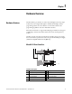
Chapter 2 About Your Controller • Install emergency-stop switches and the master control relay in your system. Make certain that relay contacts have a sufficient rating for your application. Emergency-stop switches must be easy to reach. • In the following illustration, input and output circuits are shown with MCR protection. However, in most applications, only output circuits require MCR protection. The following illustrations show the Master Control Relay wired in a grounded system.
About Your Controller Chapter 2 Schematic (Using IEC Symbols) L1 L2 230V AC Disconnect Fuse MCR 230V AC I/O circuits Isolation transformer X1 115V AC X2 or 230V AC Operation of either of these contacts will remove power from the external I/O circuits, stopping machine motion. Emergency-stop push button Fuse Overtravel limit switch Stop Start Master Control Relay (MCR) Cat. No. 700-PK400A1 Suppressor Cat. No. 700-N24 MCR Suppr. MCR MCR 115V AC or 230V AC I/O circuits DC power supply.
Chapter 2 About Your Controller Schematic (Using ANSI/CSA Symbols) L1 230V AC L2 Disconnect Fuse Isolation transformer X1 115V AC or 230V AC X2 MCR Operation of either of these contacts will remove power from the external I/O circuits, stopping machine motion. Emergency-stop push button Fuse Overtravel limit switch Master Control Relay (MCR) Cat. No. 700-PK400A1 Suppressor Cat. No. 700-N24 Start Stop 230V AC output circuits MCR Suppr. MCR MCR DC power supply. Use NEC Class 2 for UL Listing.
Chapter 3 Install Your Controller Controller Mounting Dimensions Mounting Dimensions Mounting dimensions do not include mounting feet or DIN rail latches. Micro810 Controllers 2080-LC10-12AWA, 2080-LC10-12QWB, 2080-LC10-12QBB, 2080-LC10-12DWD 59 mm (2.32 in.) 91 mm (3.58 in.) 45054 74.85 mm (2.95 in.) Module Spacing Maintain spacing from objects such as enclosure walls, wireways and adjacent equipment. Allow 50.8 mm (2 in.) of space on all sides for adequate ventilation.
Chapter 3 Install Your Controller 1. Hook the top of the DIN rail mounting area of the controller onto the DIN rail, and then press the bottom until the controller snaps onto the DIN rail. 2. Push the DIN rail latch back into the latched position. Use DIN rail end anchors (Allen-Bradley part number 1492-EAJ35 or 1492-EAHJ35) for vibration or shock environments. To remove your controller from the DIN rail, pry the DIN rail latch downwards until it is in the unlatched position.
Chapter 4 Wire Your Controller Wiring Requirements WARNING: Before you install and wire any device, disconnect power to the controller system. WARNING: Calculate the maximum possible current in each power and common wire. Observe all electrical codes dictating the maximum current allowable for each wire size. Current above the maximum ratings may cause wiring to overheat, which can cause damage.
Chapter 4 Wire Your Controller of surge suppression to protect and extend the operating life of the controllers output contacts is required. Switching inductive loads without surge suppression can significantly reduce the life expectancy of relay contacts. By adding a suppression device directly across the coil of an inductive device, you prolong the life of the output or relay contacts. You also reduce the effects of voltage transients and electrical noise from radiating into adjacent systems.
Wire Your Controller Chapter 4 transient characteristic of the particular inductive device. See Recommended Surge Suppressors on page 19 for recommended suppressors. Surge Suppression for Inductive AC Load Devices Output Device Output Device Output Device Surge Suppressor RC Network Varistor Recommended Surge Suppressors Use the Allen-Bradley surge suppressors shown in the following table for use with relays, contactors, and starters.
Chapter 4 Wire Your Controller Recommended Surge Suppressors Device Coil Voltage Suppressor Catalog Number Type(4) Bulletin 509 Motor Starter Size 6 12…120V AC 199-FSMA1(2) RC 12…120V AC 199-GSMA1(3) MOV AC coil Not Required 24…48V DC 199-FSMA9 50…120V DC 199-FSMA10 130…250V DC 199-FSMA11 6…150V AC/DC 700-N24 RC 24…48V AC/DC 199-FSMA9 MOV 50…120V AC/DC 199-FSMA10 130…250V AC/DC 199-FSMA11 6…300V DC 199-FSMZ-1 Diode 6…150V AC/DC 700-N24 RC Bulletin 700 R/RM Relay Bulleti
Wire Your Controller Chapter 4 Micro810 Controllers 2080-LC10-12AWA Input Terminal Block L1 VAC 1 L2/N VAC 2 3 L2/N VAC I-00 4 5 NC I-02 6 7 I-04 8 9 I-03 I-01 I-06 10 11 I-05 12 I-07 45055 Output Terminal Block CM0 1 CM1 2 3 O-00 CM2 4 5 O-01 CM3 6 7 O-02 8 O-03 45059 2080-LC10-12QWB Input Terminal Block(1) +DC24 1 COM0 2 3 -DC24 I-01 4 5 I-00 I-03 6 7 I-02 I-04 8 9 -DC24 I-06 10 11 I-05 12 I-07 45056 Output Terminal Block CM0 1 CM1 2
Chapter 4 Wire Your Controller install the Micro800 system in a properly rated (for example, NEMA) enclosure. Make sure that the Micro800 system is properly grounded. A system may malfunction due to a change in the operating environment after a period of time. We recommend periodically checking system operation, particularly when new machinery or other noise sources are installed near the Micro800 system.
Wire Your Controller Chapter 4 Ground Your Analog Cable Use shielded communication cable (Belden #8761). The Belden cable has two signal wires (black and clear), one drain wire, and a foil shield. The drain wire and foil shield must be grounded at one end of the cable. Foil shield Black wire Insulation Drain wire Clear wire IMPORTANT 44531 Ground the drain wire and foil shield at field side. Wiring Examples Examples of sink/source, input/output wiring are shown below.
Chapter 4 Wire Your Controller Sink input wiring example Com ~ I/P 24V DC + Fuse 45627 Source output wiring example +V DC Logic side Fuse User side S OUT + G Load – 24V Supply D DC COM Micro800 Source Output 45626 Source input wiring example Com ~ I/P Fuse + 24V DC 24 45625 Rockwell Automation Publication 2080-UM001D-EN-E - September 2012
Chapter 5 Troubleshooting Status Indicators on the Controller Micro810 Controllers Status Indicator Status Indicator on the Controller State During Normal Operation During Firmware Update or Program/Data Transfer Off No power applied to device, or in Fault mode No power applied to device, or in Fault mode Solid green Device operating normally Program transfer successful Flashing green Operating System error Firmware update in progress Status Indicators on the LCD Module If you are using the
Chapter 5 Troubleshooting If an error persists after performing the recommended action, contact your local Rockwell Automation technical support representative. For contact information, go to http://support.rockwellautomation.com/MySupport.asp. List of Error Codes for Micro800 controllers Error Code Description Recommended Action 0xF000 The controller was unexpectedly reset due to a noisy environment or an internal hardware failure. The Micro800 controller program has been cleared.
Troubleshooting Chapter 5 List of Error Codes for Micro800 controllers Error Code Description Recommended Action 0xF010 The user program contains a function/ function block that is not supported by the Micro800 controller. Perform the following: • Modify the program so that all functions/function blocks are supported by the Micro800 controller. • Build and download the program using Connected Components Workbench. • Put the Micro800 controller on Run mode.
Chapter 5 Troubleshooting List of Error Codes for Micro800 controllers Error Code Description Recommended Action 0xF023 The controller program has been cleared. This happened because: • Download or transfer the program. • a power down occurred during program download or transfer from the memory module. • the Flash Integrity Test failed (Micro810 only). 0xF050 The embedded I/O configuration in the user program is invalid.
Troubleshooting Chapter 5 List of Error Codes for Micro800 controllers Error Code Description 0xF8A1 The DOY parameters are invalid. Recommended Action Perform the following: • Correct the program to ensure that there are no invalid parameters. • Build and download the program using Connected Components Workbench. • Put the Micro800 controller on Run mode. 0xF8A2 The HSC parameters are invalid. Perform the following: • Correct the program to ensure that there are no invalid parameters.
Chapter 5 Troubleshooting Controller Error Recovery Model Identify the error code and description. No Use the following error recovery model to help you diagnose software and hardware problems in the micro controller. The model provides common questions you might ask to help troubleshoot your system. Refer to the recommended pages within the model for further help. Is the error hardware related? Start Yes Refer to page 25 for probable cause and recommended action.
Troubleshooting Calling Rockwell Automation for Assistance Chapter 5 If you need to contact Rockwell Automation or local distributor for assistance, it is helpful to obtain the following (prior to calling): • controller type, series letter, revision letter, and firmware (FRN) number of the controller • controller indicator status Rockwell Automation Publication 2080-UM001D-EN-E - September 2012 31
Chapter 5 Troubleshooting Notes: 32 Rockwell Automation Publication 2080-UM001D-EN-E - September 2012
Chapter 6 Program Execution in Micro800 Configure and Program Your Micro810 Controller The Micro810 controller can be configured by either: • using Smart Relay function blocks using the 2080-LCD display (and without the use of Connected Components Workbench programming software), or • programmed as a full feature microcontroller using Connected Components Workbench. You cannot use both the Smart Relay function blocks and also download a Connected Components Workbench program.
Chapter 6 Program Execution in Micro800 order. You can view and modify an order number for a program from the program's properties. However, the Project Organizer does not show the new order until the next time the project is opened. The Micro800 supports jumps within a program. Call a subroutine of code within a program by encapsulating that code as a User Defined Function Block (UDFB). Although a UDFB can be executed within another UDFB, a maximum nesting depth of five is supported.
Program Execution in Micro800 Chapter 6 In a case where bindings are defined, variables consumed by a resource are updated after the inputs are scanned and the variables produced for other resources are sent before updating inputs. When a cycle time is specified, a resource waits until this time has elapsed before starting the execution of a new cycle. The POUs execution time varies depending on the number of active steps in SFC programs and instructions such as jumps, IFs, and returns.
Chapter 6 Program Execution in Micro800 System Time Variable for Programmed Cycle Time Memory Allocation Variable Type Description __SYSVA_TCYCYCTIME TIME Programmed cycle time. Note: Programmed cycle time only accepts values in multiples of 10 ms. If the entered value is not a multiple of 10, it will be rounded up to the next multiple of 10. Available memory on Micro810 controllers is shown in the table below.
Program Execution in Micro800 Chapter 6 • A User Defined Function Block (UDFB) can be executed within another UDFB, with a limit of 5 nested UDFBs. Avoid creating UDFBs with references to other UDFBs, as executing these UDFBs too many times may result in a compile error. Example of 5 nested UDFBs Program UDFB1 UDFB2 UDFB3 UDFB4 UDFB5 • Structured Text (ST) is much more efficient and easier to use than Ladder Logic, when used for equations.
Chapter 6 Program Execution in Micro800 Notes: 38 Rockwell Automation Publication 2080-UM001D-EN-E - September 2012
Chapter 7 Controller Security Micro800 security generally has two components: • Exclusive Access which prevents simultaneous configuration of the controller by two users • Controller Password Protection which secures the Intellectual Property contained within the controller and prevents unauthorized access Additionally, for Micro810 controllers, the 2080-LCD has a password feature to secure the LCD display.
Chapter 7 Controller Security The controller password is also backed up to the memory backup module (that is, 2080-MEMBAK-RTC for Micro830 and Micro850 and 2080-LCD for Micro810 controllers). If the password in the backup module is different from the memory backup module, then restore operation will fail. TIP Compatibility For instructions on how to set, change, and clear controller passwords, see Configure Controller Password on page 279.
Controller Security Chapter 7 Upload from a Password-Protected Controller 1. Launch the Connected Components Workbench software. 2. On the Device Toolbox, expand Catalog by clicking the + sign. 3. Select the target controller. 4. Select Upload. 5. When requested, provide the controller password.
Chapter 7 Controller Security controller in the Micro800 project, and then downloading to controller2. Finally, controller2 will be locked. 1. On the Device Toolbox, open Discover and click Browse Connections. 2. Select target controller1. 3. When requested, enter the controller password for controller1. 4. Build and save the project. 5. Click Disconnect. 6. Power down controller1. 7. Swap controller1 hardware with controller2 hardware. 8. Power up controller2. 9. Click Connect. 10.
Controller Security Chapter 7 ATTENTION: The project in the controller will be lost but a new project can be downloaded.
Chapter 7 Controller Security Notes: 42 Rockwell Automation Publication 2080-UM001D-EN-E - September 2012
Appendix A Specifications Micro810 Controllers General – 2080-LC10-12AWA, 2080-LC10-12QWB, 2080-LC1012DWD, 2080-LC10-12QBB Attribute 2080-LC10-12AWA 2080-LC10-12QWB Number of I/O 8 Input (4 digital, 4 analog/digital, configurable) 4 Output Dimensions HxWxD 91 x 75 x 59 mm (3.58 x 2.95 x 2.32 in.) Supply voltage range 85…263V 20.4…26.
Appendix A Specifications Non-isolated AC Inputs (2080-LC10-12AWA) Attribute Value On-state voltage, nom 120/240V AC On-state voltage, min 79V AC On-state voltage, max 265V AC Off-state voltage, max 40V AC Off-state current, max 0.095 mA Operating frequency, nom 50/60 Hz Input impedence 423.
Specifications Appendix A Analog Inputs (2080-LC10-12QWB, 2080-LC10-12QBB, 2080-LC10-12DWD) (Inputs 4…7) Attribute Value Input type DC voltage Input voltage range 0…10V DC Input voltage, max 26.4V DC Value of LSB 10 mV Input resolution 10-bit Input data count range 0…1023 Smoothing None, smoothing Overall accuracy 5% of full-scale (2% with calibration) (25…55 °C) (77…131 °F) Noise rejection 50/60 Hz Common mode rejection 40 dB, DC to 60 Hz with smoothing filter Nominal impedance 14.
Appendix A Specifications Relay Output Life Attribute Value Mechanical 10,000,000 cycles Electrical with rated load 50,000 cycles Embedded RTC Attribute Value Resolution READ_RTC() 1 sec Accuracy ± 12 sec/month @ 25 °C ± 160 sec/month @ 0…55 °C Power off Supercap — 5 days @ 40 °C or lower Supercap life — 5 years @ 40 °C, 14.
Specifications Appendix A Micro810 Low Current Relay Chart Relay life with load DC 30 V resistive load Number of operations (X104) 100 50 30 20 AC 125 V resistive load 10 AC 250 V resistive load AC 125 V cos Θ = 0.4 DC 30 V T = 7 ms 5 AC 250 V cos Θ = 0.4 3 0.5 1.0 2.0 3.0 4.0 5.0 Switching capacity (A) Maximum Volts IEC 947 Amperes Amperes Continuous Make Break Volt-Amperes Make Break 120V AC AC-15 15 A 1.5 A 4A 1800V A 180V A 240V AC AC-15 7.5 A 0.
Appendix A Specifications Environmental 50 Attribute Value Temperature, operating IEC 60068-2-1 (Test Ad, Operating Cold), IEC 60068-2-2 (Test Bd, Operating Dry Heat), IEC 60068-2-14 (Test Nb, Operating Thermal Shock): 0…55 °C (32…131 °F) Temperature, surrounding air, max 55 °C (131 °F) Temperature, storage IEC 60068-2-1 (Test Ab, Unpackaged Non-operating Cold), IEC 60068-2-2 (Test Bb, Unpackaged Non-operating Dry Heat), IEC 60068-2-14 (Test Na, Unpackaged Non-operating Thermal Shock): -40…85 °C
Specifications Appendix A Certifications Certification (when product is marked)(1) Value c-UL-us UL Listed Industrial Control Equipment, certified for US and Canada. See UL File E322657. UL Listed for Class I, Division 2 Group A,B,C,D Hazardous Locations, certified for U.S. and Canada. See UL File E334470.
Appendix A Specifications Micro800 Programmable Controller External AC Power Supply General Attribute Value Dimensions, HxWxD 90 x 45 x 80 mm (3.55 x 1.78 x 3.15 in.) Shipping weight 0.34 kg (0.75 lb) Supply voltage 52 range(1) 100V…120V AC, 1 A 200…240V AC, 0.5 A Supply frequency 47…63 Hz Supply power 24V DC, 1.6 A Inrush current, max 24A @ 132V for 10 ms 40A @ 263V for 10 ms Power consumption (Output power) 38.4 W @ 100V AC, 38.4 W @ 240V AC Power dissipation (Input power) 45.
Appendix B About Accessories Accessories This chapter highlights the accessories you can use with the Micro810 controller. External AC Power Supply Use this optional power supply (2080-PS120-240VAC) in applications with smaller systems when a 24V DC power supply is not readily available. Wire the Module PAC-1 PAC-2 PAC-3 45062 DC-1 DC-2 DC-3 DC-4 45061 AC Input Connectors DC Output Connectors (DC 24V/ 1.
Chapter B About Accessories 1.5" LCD Display and Keypad Module This module (2080-LCD) also functions as a backup memory module for the Micro810 controller. This module offers an affordable and simple method of viewing status and configuring the Micro810 Controller. With this LCD module, you can also modify core Smart Relay function blocks. The LCD Display instructions can be used to display custom messages as well as to read keystrokes.
About Accessories Chapter B Access the Main Menu Press the ESC and OK buttons at the same time to access the Main Menu screen. Use the arrow keys to move the cursor up or down to the item you want to select. Mode Switch Set the controller to Program Mode or Run mode from this screen. SR Function Use the LEFT and RIGHT arrow keys to select the parameters. Use the UP and DOWN arrow keys to set the value for a parameter. Variable Monitor or set values for programdefined variables.
Chapter B About Accessories USB Adapter This module (2080-USBADAPTER) provides the Micro810 controller with a USB port. Use a standard USB A Male to B Male cable for programming the controller.
Appendix C Quickstarts This appendix covers some common tasks for the Micro810 controller.
Appendix C Quickstarts Activate Password Passwords can be set in the System menu in both Run or Stop operating modes. If, however, a password is already activated, you will not be able to access most of the items from the System menu unless you deactivate the password. 1. Press Esc and OK to call up the System menu. 2. Select the menu item SECURITY. 3. Press the OK button and select Activate PWD. 4. Press the OK button again to access the password entry area. 5.
Quickstarts Appendix C 3. Press the OK button and select Deactivate PWD. Deactivate Password option is available only if a password has been previously set. 4. Enter the password you have previously set using the arrow buttons. – left and right arrows move to the 8-digit entry field – left and right arrows select digit in password – up and down arrows set a value between 0 and 9. The following message appears when the deactivation is successful: 5. Press OK.
Appendix C Quickstarts 4. Enter the OLD password you have previously set using the arrow buttons. – left and right arrows move to the 8-digit entry field – left and right arrows select digit in password – up and down arrows set a value between 0 and 9. 5. Enter the New Password using the arrow buttons. 6. Press OK. Delete Password TIP Deleting the password effectively unlocks the LCD. On the next controller power cycle, a password will not be required to access system functions on the LCD.
Quickstarts Appendix C – up and down arrows set a value between 0 and 9. 5. Enter the New Password as 00000000 to delete the password. Use the arrow buttons as in the previous step. 6. Press OK.
Appendix C Quickstarts Configure Controller Password Set, change, and clear the password on a target controller through the Connected Components Workbench software. IMPORTANT The following instructions are supported on Connected Components Workbench revision 2 and Micro800 controllers with firmware revision 2. For more information about this feature, see Controller Security on page 235.
Quickstarts Appendix C 4. Click Secure button. Select Set Password. 5. The Set Controller Password dialog appears. Provide password. Confirm the password by providing it again in the Confirm field. TIP Passwords must have at least eight characters to be valid. 6. Click OK. The Confirmation dialog box appears to confirm that the password has been set successfully. 7. Click OK.
Appendix C Quickstarts Once a password is created, any new sessions that try to connect to the controller will have to supply the password to gain exclusive access to the target controller. Change Password With an authorized session, you can change the password on a target controller through the Connected Components Workbench software. The target controller must be in Connected status. 1. On the Device Details toolbar, click Secure button. Select Change Password. 2.
Quickstarts Appendix C 3. Click OK. The Confirmation dialog box appears to confirm that the password has been set successfully. 4. Click OK. The controller will require the new password to grant access to any new session. Clear Password With an authorized session, you can clear the password on a target controller through the Connected Components Workbench software. 1. On the Device Details toolbar, click Secure button. Select Clear Password. 2. The Clear Password dialog appears. Enter Password. 3.
Appendix C Quickstarts Use the Micro810 Smart Relay Functionality The Micro810 12-point (8 Inputs and 4 Outputs) controller comes with a builtin smart relay function that can be configured using the optional LCD Display and push buttons to control four relay outputs (O00…O03), without using any software.
Quickstarts Appendix C Navigate the LCD Display Language Allows user to select English, Chinese, French, Spanish, Italian Micro810 splash screen Appears briefly upon controller power up Navigation buttons Allows user to navigate, select, confirm, and undo selection Password activated A button sign indicates password protection for LCD operation is activated. For example, a user could change from Run mode to Program mode using LCD buttons. Note that this password is for LCD access only.
Appendix C Quickstarts 2. The status display shows PROG mode, the day and time, and the I/O status. Press the ESC and OK buttons buttons at the same time to go to the Main Menu. 3. Press the DOWN arrow button to navigate to SR Function. Press the OK button. The function block for controlling Output 0 is displayed. 4. Press the UP arrow button once to navigate to the function block controlling Output 1. UP RIGHT 5. Press the RIGHT arrow button once.
Quickstarts Appendix C c. Press RIGHT arrow button once to go to the last digit. Press the DOWN arrow button five times to set the last digit to 3. PV value 9. Press the RIGHT arrow button once to navigate to the screen selection parameter. Screen selection parameter 10. Press the OK button to submit the parameter changes. A message prompts you to save the parameter changes. Press the OK button to save the changes.
Appendix C Quickstarts the preset value PV, and energizes output O1 when CV > PV. To test the operation, we connect a count push button to I02, a reset push button to I03, and a pilot light to output O01. 1. Press the ESC button to return to the Main Menu. 2. Press the UP arrow button once to go to Mode Switch. Press the OK button. 3. Press the DOWN arrow button once to select RUN mode. Press the OK button.
Quickstarts Appendix C 4. Press the OK button to confirm the RUN mode selection. 5. The screen indicates that the controller is in RUN mode. Press the ESC button to return to the Main Menu. 6. Press the DOWN arrow button once to navigate to SR Function. a. Press the UP arrow button once to go to CTU function block. 7. Press and release the count push button. The current value CV increments to 00001.
Appendix C Quickstarts a. Press and release the count push button. The current value CV increments to 00002. b. Press and release the count push button. The current value CV increments to 00003. Since the current value CV = present value PV, the output O1 is energized, and the pilot light turns on. c. Press and release the Reset push button. The current value CV is reset to zero, and output O1 is de-energized. The pilot light turns off.
Quickstarts Appendix C Configure On-delay Timing (TON) TON – Sample parameter configuration Parameter Field Configuration Value Q Q00 IN I01 Time Resolution SS:MS PT 15:000 1. Power up the Micro810 controller. The Micro810 splash screen briefly appears after follow up. 2. The status display shows PROG mode, the day and time, and the I/O status. Press the ESC and OK buttons at the same time to navigate to the Main Menu. 3. Press the DOWN arrow button to navigate to SR Function.
Appendix C Quickstarts 9. Press the RIGHT arrow button once to select the first digit entry in PT parameter field. First digit entry for PT parameter To change the PT parameter value to 15:000, do the following steps: a. Press the UP arrow button once to turn the first digit entry to 1. b. Press the RIGHT button arrow once to select the second entry in PT parameter field. c. Press the UP arrow button five times to increment the digit value to 5. d.
Quickstarts Appendix C 6. Press the DOWN arrow button once and select SR FUNCTION. Press the OK button. The TON function block to control Output 0 becomes available. 7. Press the push button connected to I01. ET starts to elapse. 8. When the current ET equals PT, output O00 is energized, and the pilot light turns on. Configure DOY DOY – Sample Parameter Configuration Parameter Field Configuration Value Q Q03 Channel A EN I03 Y/C 0 On 11/08/18 (YY/MM/DD) Off 11/08/19 (YY/MM/DD) 1.
Appendix C Quickstarts 5. Press the RIGHT arrow button once to select the DOY instruction parameter field. 6. Press the RIGHT arrow button once. The CHANNEL parameter field is selected and it shows CHANNEL A. Channel parameter 7. Press the RIGHT arrow button to select the EN parameter field. Press the DOWN arrow button four times to change the EN parameter value to I03. 8. Press the RIGHT arrow button twice to select the first digit entry in the ON parameter field.
Quickstarts Appendix C 9. Press the RIGHT arrow button once to select the first entry in the OFF parameter field. Change the Off date settings to 11/08/19 (YY/MM/DD). To do this, follow these steps: a. Press the RIGHT arrow button once to select the second entry in the OFF parameter field. Then, press the UP arrow button once to get the digit value of 1. b.
Appendix C Quickstarts 3. Press the DOWN arrow button thrice to go to Clock Setup then press the OK button. Press the OK button again on Clock. 4. Press the RIGHT arrow button to navigate through Year, MM.DD, and HH:MM fields. Set the MM.DD field value to the On date established during configuration (11/08/18). Use the UP or DOWN arrow buttons to increase or decrease the digit values on the MM.DD field. 5. Go to the HH:MM field.
Quickstarts Appendix C 7. Press the push button connected to I03. If the value of RTC is in the range of Year-Time setting for CHANNEL A, then the pilot light turns on. Configure TOW TOW – Sample Parameter Configuration Parameter Field Configuration Value Q Q02 Channel A EN I03 D/W 0 On MO-08:30 Off MO-08:31 1. Power up the Micro810 controller. The Micro810 splash screen briefly appears after power up. 2. The I/O status display shows PROG mode, the day and time, and the I/O status.
Appendix C Quickstarts 4. Press the UP arrow button twice to navigate to the function block for Output 2 (TOW). 5. Press the RIGHT arrow button once to select the TOW instruction parameter field. 6. Press the RIGHT arrow button once to select CHANNEL parameter field. It shows CHANNEL A. 7. Press the RIGHT arrow button once to select the EN parameter field. Press the DOWN arrow button once to change the EN parameter value to I03. 8. Press the RIGHT arrow button once to select the D/W parameter field. 9.
Quickstarts Appendix C c. Press the RIGHT arrow button twice to get to the fifth digit entry in the OFF parameter field, and press the UP arrow button once to get the digit value of 1. 11. Press the OK button to submit the parameter changes. A screen confirms your request to save the parameter changes. Press the OK button to save the changes.
Appendix C Quickstarts 4. Press the RIGHT arrow button to navigate through Year, MM.DD, and HH:MM fields. Set the MM.DD field value to a date that falls on a Monday, as set in the Configure example. Use the UP or DOWN arrow buttons to increase or decrease the digit values on the MM.DD field. 5. Go to the HH:MM field. Change the time setting to 08:29, or a minute before the On time set. Use the UP or DOWN arrow buttons to increase or decrease the digit values on the HH:MM field.
Quickstarts Appendix C 8. Press the push button connected to I03. If the value of RTC is in the range of Day-Time setting for CHANNEL A, the pilot light turns on. Configure Countdown (CTD) CTD – Sample Parameter Configuration Parameter field Configuration value Q Q00 CLK I01 LOAD I02 PV 00010 1. Power up the Micro810 controller. The Micro810 splash screen briefly appears after power up. 2. The status display shows the PROG status, the day and time, and the I/O status.
Appendix C Quickstarts 6. Press the RIGHT arrow button once to select the CLK parameter field. This is the trigger for counting. Press the UP arrow button once to change CLK parameter to I01. 7. Press the RIGHT arrow button once to select the LOAD parameter field. This input reloads the preset value PV. Press the UP arrow button once to select I02. 8. Press the RIGHT arrow button three times to move to the first non-zero entry on the PV (Preset Value for the counter) parameter field. a.
Quickstarts Appendix C 2. Press the UP arrow button once to select Mode Switch and press the OK button. 3. Press the DOWN arrow button once to select RUN mode. Press the OK button. 4. Press the OK button to confirm the RUN mode selection. 5. The screen indicates that the controller is in RUN mode. Press the ESC button to return to the Main Menu. 6. Press the DOWN arrow button once and press the OK button to select SR FUNCTION. 7. Press the load push button connected to I02.
Appendix C Quickstarts 8. Press and release the count push button connected to I01. The current value CV decrements to 00009. Repeat the step 8 nine times, until CV decrements to 00000. When CV = 0, the output O00 is energized, and the pilot light turns off. Configure TONOFF TONOFF – Sample Parameter Configuration Parameter field Configuration value Q Q01 IN I03 Time Resolution SS:MS PT 15:000 PTOFF 20:000 1. Power up the Micro810 controller.
Quickstarts Appendix C 6. Press the DOWN arrow button twice to go to TONOFF instruction. 7. Press the RIGHT arrow button once to select the IN parameter field. This input marks the start for the internal timer. Press the UP arrow button once to change IN parameter value to I03. 8. Press the RIGHT arrow button once to select the Time-Resolution parameter field. This input determines the unit of internal timer. Press the DOWN arrow button once to change time setting to SS:MS. 9.
Appendix C Quickstarts Test the TONOFF Predefined Function The TONOFF instruction starts an internal timer up to a given value PT when input IN makes a transition from low to high, and energizes the output when ET = PT. Restart the internal timer up to a given value PTOF when input IN makes a transition from high to low, and de-energize the output when EP=PTOF. To test the operation, we connect a push button to I03, and a pilot light to output O01. 1. Press the ESC button to return to the Main Menu. 2.
Quickstarts Appendix C 10. Release the push button connected to I03. The elapsed time ET restarts to elapse. When the current elapsed time ET = programmed time PTOF, the output O01 is de-energized, and the pilot light turns off. Configure Pulse Timing (TP) TP – Sample Parameter Configuration Parameter Field Configuration Value Q Q02 IN I03 Time Resolution SS:MS PT 15:000 1. Power up the Micro810 controller. The Micro810 splash screen briefly appears. 2.
Appendix C Quickstarts d. Press the RIGHT arrow button twice to select the fourth digit entry in PT parameter field. e. Press the DOWN arrow button once to get the digit value of zero. 8. Press the OK button to submit the parameter changes. A screen confirms your request to save the parameter changes. Press the OK button to save the changes.
Quickstarts Appendix C 8. Press the push button connected to I03. The elapsed time ET starts to elapse and the pilot light turns on. When the current elapsed time ET = programmed time PT, the output O02 is de-energized, and the pilot light turns off. Configure TOF TOF – Sample Parameter Configuration Parameter field Config value Q Q03 IN I02 Time Resolution SS:MS PT 15:000 1. Power up the Micro810 controller. The Micro810 splash screen briefly appears after power up. 2.
Appendix C Quickstarts 6. Press the RIGHT arrow button once to select the IN parameter field. This marks the start for the Off-delay timer. Press the DOWN arrow button four time to change IN parameter value to I02. 7. Press the RIGHT arrow button once to select the Time-Resolution parameter field. This input determines the unit of Off-delay timer. Press the DOWN arrow button once to change time parameter setting to SS:MS. 8.
Quickstarts Appendix C given value PT, it de-energizes the output. To test the operation, we connect a push button to I02, and a pilot light to output O03. 1. Press the ESC button to return to the Main Menu. 2. Press the UP arrow button once to select Mode Switch. Press the OK button. 3. Press the DOWN arrow button once to select RUN mode. Press the OK button. 4. Press the OK button to confirm the RUN mode selection. 5. The screen indicates that the controller is in RUN mode.
Appendix C Quickstarts Flash Update the Micro800 Firmware IMPORTANT When the controller is in Remote Run mode, and it is password protected, the user needs to supply the correct password to switch to Remote Program to enable upgrade. The Micro810 controller does not include a reset-to-factory-default button and a mechanical switch to change modes that will override password protection to allow a flash upgrade.
Quickstarts Appendix C 2. Start ControlFLASH and click Next. 3. Select the catalog number of the Micro800 controller that you are going to update and click Next.
Appendix C Quickstarts 4. Select the controller in the browse window and click OK. 5. If you see the following screen (Micro810 controller only), leave the Slot Number at 0 and click OK.
Quickstarts Appendix C 6. Click Next to continue, and verify the revisions. Click Finish, and Yes to initiate the update.
Appendix C Quickstarts The next screen shows the download progress. 7. If you see an error message instead, check to see if the controller is faulted or in Run mode. If so, clear the fault or switch to Program mode, click OK and try again. 8. When the flash update is complete, you see a status screen similar to the following. Click OK to complete the update.
Quickstarts Establish Communication Between RSLinx and a Micro810 12-point controller through USB Appendix C This quickstart shows you how to get RSLinx RSWho to communicate with a Micro810 12-point controller through USB. Normally, RSLinx Classic is installed as part of the Connected Components Workbench software installation process. The minimum version of RSLinx Classic with full Micro800 controller support is 2.57, build 15 (released March 2011). 1. Power up the Micro810 12-point controller. 2.
Appendix C Quickstarts 4. Click Next to continue. 5. Click Finish after Found New Hardware Wizard completes installation of the software. 6. Open RSLinx Classic and run RSWho by clicking the icon. 7. The Micro810 controller shows up under the 12PtM810 driver. 8. You can now use ControlFLASH or Connected Components Workbench to communicate with the Micro810 controller.
Quickstarts Forcing I/O Appendix C Forcing is only possible with I/O and does not apply to user defined variables and non-I/O variables. Inputs are logically forced, so LED status indicators do not show forced values, but the inputs in the user program are forced. Unlike inputs, outputs are physically forced, so LED status indicators do show forced values. The user program does not use forced values. The following diagram illustrates forcing behaviour.
Appendix C Quickstarts Remember you cannot force a Physical Input and cannot force a Logical Output. In many cases, the front of the controller is not visible to the operator and Connected Components Workbench is not online with the controller.
Appendix D IPID Function Block This function block diagram shows the arguments in the IPIDCONTROLLER function block. IPIDCONTROLLER ENO EN Process Output SetPoint AbsoluteError FeedBack ATWarning OutGains Auto Initialize Gains AutoTune ATParameters The following table explains the arguments used in this function block. IPIDCONTROLLER Arguments Parameter Parameter Type Data Type Description EN Input BOOL Function block enable When EN = TRUE, execute function.
Appendix D IPID Function Block IPIDCONTROLLER Arguments Parameter Parameter Type Data Type Description AutoTune Input BOOL Start AutoTune sequence ATParameters Input AT_Param Auto tune parameters See AT_Param Data Type Output Output Real Output value from the controller AbsoluteError Output Real AbsoluteError is the difference between Process value and set point value ATWarnings Output DINT Warning for the Auto Tune sequence.
IPID Function Block Appendix D AT_Param Data Type Parameter Type Description Step REAL Step value for AutoTune. Must be greater than noise band and less than ½ load. ATDynamSet REAL Auto Tune time. Set the time to wait for stabilization after the step test (in seconds). Auto Tune process will be stopped when ATDynamSet time expires. ATReset BOOL Determines whether the output value is reset to zero after an AutoTune sequence: • True – Reset IPIDCONTROLLER output to zero after Auto tune process.
Appendix D IPID Function Block PID Application Example Water In Water Level Tank Water Out The illustration above shows a basic water level control system, to maintain a preset water level in the tank. A solenoid valve is used to control incoming water, filling the tank at a preset rate. Similarly, outflowing water is controlled at a measureable rate. IPID Autotuning for First and Second Order Systems Autotune of IPID can only work on first and second order systems.
IPID Function Block Appendix D energy for the former and the inductive and capacitive storage energy for the latter. Motor drive systems and heating systems can be typically modeled by the LR and C electric circuit. PID Code Sample The illustration above shows sample code for controlling the PID application example shown before. Developed using Function Block Diagrams, it consists of a pre-defined function block, IPIDCONTROLLER, and four user-defined function blocks.
Appendix D IPID Function Block • PID_PWM This user defined function block provides a PWM function, converting a real value to a time related ON/OFF output. • SIM_WATERLVL This user defined function block simulates the process depicted in the application example shown before. IMPORTANT User Program Scan Time is Important The autotuning method needs to cause the output of the control loop to oscillate.
Index Numerics 1.
Index L LCD Password activate 60 change 61 deactivate 60 delete 62 lock states 41 low current relay chart 52 M master control relay 12 emergency-stop switches 13 using ANSI/CSA symbols schematic 15 using IEC symbols schematic 14 master control relay circuit periodic tests 10 memory allocation 36 Micro800 power supply 1 Micro810 12-Point Controllers 1 module spacing 17 motor starters (bulletin 509) surge suppressors 21 mounting dimensions 17 P panel mounting 18 PID Application Example 108 PID Code Sample
Rockwell Automation Support Rockwell Automation provides technical information on the Web to assist you in using its products. At http://www.rockwellautomation.com/support/, you can find technical manuals, a knowledge base of FAQs, technical and application notes, sample code and links to software service packs, and a MySupport feature that you can customize to make the best use of these tools.