
User Manual

Installing the Adapter 2-3
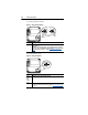
1. Remove power from the drive.
2. Use static control precautions.
3. Connect an RS-485 cable to the network, and route it through the
bottom of the PowerFlex drive.
4. Connect a 6-pin linear plug to the RS-485 cable.
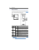
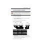
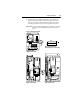
Figure 2.3 Example Network Connections
(1) The shield must be grounded at a single point on the network (jumper terminals
SHIELD and GND).
(2) Jumper Terminals TERM and A on the adapters at end of the RS-485 network. This
enables a built in RC termination network on the adapter.
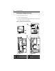
5. Connect the cable to the adapter.
Connecting the Adapter to the Network
!
ATTENTION: Risk of injury or death exists. The PowerFlex drive
may contain high voltages that can cause injury or death. Remove
power from the drive, and then verify power has been discharged before
installing or removing an adapter.
Terminal Signal Function
GND CHASSIS GND
(1)
Shield GND termination
SHIELD SHIELD Shield RC termination
COM COMMON Signal Common
B Signal B Tx Rx D-
A Signal A Tx Rx D+
TERM TERMINATION
(2)
Signal RC termination
Node 1 Node 2 Node "n"
TERM
A
B
COM
SHIELD
GND
TERM
A
B
COM
SHIELD
GND
TERM
A
B
COM
SHIELD
GND