RS-485 DF1 Adapter 20-COMM-S FRN 1.
Important User Information Solid state equipment has operational characteristics differing from those of electromechanical equipment. “Safety Guidelines for the Application, Installation and Maintenance of Solid State Controls” (Publication SGI-1.1) describes some important differences between solid state equipment and hard-wired electromechanical devices.
Summary of Changes This is the first release of the RS-485 DF1 FRN 1.xxx.
2 Notes:
Table of Contents Preface About This Manual Related Documentation . . . . . . . . . . . . . . . . . . . . . . . . . . . . . P-1 Conventions Used in this Manual . . . . . . . . . . . . . . . . . . . . . P-2 Rockwell Automation Support. . . . . . . . . . . . . . . . . . . . . . . . P-2 Chapter 1 Getting Started Components . . . . . . . . . . . . . . . . . . . . . . . . . . . . . . . . . . . . . . Features . . . . . . . . . . . . . . . . . . . . . . . . . . . . . . . . . . . . . . . . .
ii Table of Contents Appendix A Specifications Communications . . . . . . . . . . . . . . . . . . . . . . . . . . . . . . . . . . A-1 Electrical . . . . . . . . . . . . . . . . . . . . . . . . . . . . . . . . . . . . . . . . A-1 Mechanical . . . . . . . . . . . . . . . . . . . . . . . . . . . . . . . . . . . . . . . A-1 Environmental . . . . . . . . . . . . . . . . . . . . . . . . . . . . . . . . . . . . A-2 Regulatory Compliance . . . . . . . . . . . . . . . . . . . . . . . . . . . . .
Preface About This Manual Topic Related Documentation Conventions Used in this Manual Rockwell Automation Support Page P-1 P-2 P-2 Related Documentation For: DF1 Protocol DriveExplorer™ Refer to: DF1 Protocol and Command Set Reference manual DriveExplorer Getting Results Manual Online help (installed with the software) DriveTools 2000™ http://www.ab.
P-2 About This Manual Conventions Used in this Manual The following conventions are used throughout this manual: • • • Parameter names are shown in the following format Parameter xxx - [*]. The xxx represents the parameter number. The * represents the parameter name. For example Parameter 01 - [DPI Port]. Menu commands are shown in bold type face and follow the format Menu > Command. For example, if you read “Select File > Open,” you should click the File menu and then click the Open command.
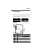
Chapter 1 Getting Started The RS-485 DF1 (20-COMM-S) is an embedded communication option for any one drive in the PowerFlex 7-Class family. It can also be used with other Allen-Bradley products implementing DPI™, a functional enhancement to SCANport™. Topic Components Features Compatible Products Required Equipment Page 1-1 1-2 1-3 1-3 Topic Safety Precautions Quick Start Modes of Operation Page 1-4 1-5 1-6 Components Figure 1.
1-2 Getting Started Features The RS-485 DF1 adapter features the following: • The adapter is mounted in and receives power from the PowerFlex drive. Captive screws are used to secure and ground the adapter to the drive. • Switches let you set a node address and network data rate before applying power to the PowerFlex drive. Alternatively, you can disable the switches and use parameters to configure these features.
Getting Started 1-3 Compatible Products DPI is a second generation peripheral communication interface (see Glossary). The RS-485 DF1 adapter is compatible with Allen-Bradley PowerFlex drives and other products that support DPI. DPI is a functional enhancement to SCANport.
1-4 Getting Started Safety Precautions Please read the following safety precautions carefully . ! ! ! ! ! ! ATTENTION: Risk of injury or equipment damage exists. Only personnel familiar with drive and power products and the associated machinery should plan or implement the installation, start-up, configuration, and subsequent maintenance of the product using a RS-485 DF1 adapter. Failure to comply may result in injury and/or equipment damage. ATTENTION: Risk of injury or death exists.
Getting Started 1-5 Quick Start This section is designed to help experienced users configure or set up the RS-485 DF1 adapter. If you are unsure how to complete a step, refer to the referenced chapter. Step 1 Review the safety precautions for the adapter. 2 Verify that the PowerFlex drive is properly installed. 3 Commission the adapter. Set a unique node address and the appropriate data rate using the switches on the adapter. If desired, you can disable the switches and use parameter settings instead.
1-6 Getting Started Modes of Operation The adapter uses four status indicators to report its operating status. They can be viewed on the adapter or through the drive cover. See Figure 1.2. Figure 1.2 Status Indicators (location on drive may vary) ➊ ➋ PWR STS ➌ ➍ PORT MOD NET A NET B # ➊ Status Indicator PORT Status(1) Description Green Normal Operation. The adapter is properly connected and is communicating with the drive. The adapter is in the process of establishing a connection to the drive.
Chapter 2 Installing the Adapter Chapter 2 provides instructions for installing the adapter on a PowerFlex drive. Topic Preparing for an Installation Commissioning the Adapter Connecting the Adapter to the Network Connecting the Adapter to the Drive Applying Power Page 2-1 2-1 2-3 2-4 2-6 Preparing for an Installation Before installing the RS-485 DF1 adapter: • Verify that you have all required equipment. Refer to Chapter 1, Getting Started.
2-2 Installing the Adapter 1. Set the node address switches. Figure 2.1 Setting the Node Address 2 2 3 4 1 0 5 9 6 8 4 0 5 9 7 6 8 7 Ones Digit Tens Digit Setting 0 – 99 3 1 Description Node address used by the adapter if switches are enabled. The default switch setting is 1. Important: If the Data Rate switch is set to “PGM” (Program), the adapter will use the setting of Parameter 03 - [DF1 Addr Cfg] for the node address. The default parameter setting is 1.
Installing the Adapter 2-3 Connecting the Adapter to the Network 1. Remove power from the drive. 2. Use static control precautions. 3. Connect an RS-485 cable to the network, and route it through the bottom of the PowerFlex drive. 4. Connect a 6-pin linear plug to the RS-485 cable. Figure 2.
2-4 Installing the Adapter Connecting the Adapter to the Drive 1. Remove power from the drive. 2. Use static control precautions. 3. Connect the Internal Interface cable to the DPI port on the drive and then to DPI connector on the adapter. Figure 2.4 DPI Ports and Internal Interface Cables ➊ ➋ RS-485 DF1 Adapter ➌ PowerFlex 70 Drive ➍ PowerFlex 700 Drive 0 - 1 Frame # ➊ ➋ Description 15.24 cm (6 in.
Installing the Adapter 2-5 4. On a PowerFlex 70, fold the Internal Interface cable behind the adapter and mount the adapter on the drive using the four captive screws. On a PowerFlex 700, just mount the adapter on the drive using the four captive screws to secure and ground it to the drive. Important: All screws must be tightened since the adapter is grounded through a screw. Recommended torque is 0.9 N-m (8.0 lb.-in.) Figure 2.
2-6 Installing the Adapter Applying Power ! ATTENTION: Risk of equipment damage, injury, or death exists. Unpredictable operation may occur if you fail to verify that parameter settings and switch settings are compatible with your application. Verify that settings are compatible with your application before applying power to the drive. 1. Close the door or reinstall the cover on the drive. The status indicators can be viewed on the front of the drive after power has been applied. 2.
Chapter 3 Configuring the Adapter Chapter 3 provides instructions and information for setting the parameters in the adapter. Topic Configuration Tools Using the PowerFlex HIM Setting the Node Address Setting the Data Rate Page 3-1 3-3 3-4 3-4 Topic Setting a Fault Action Resetting the Adapter Viewing the Adapter Configuration Page 3-5 3-7 3-8 For a list of parameters, refer to Appendix B, Adapter Parameters. For definitions of terms in this chapter, refer to the Glossary.
3-2 Configuring the Adapter Using DriveExplorer With DriveExplorer software, you can edit parameters in both the 1203-SSS serial converter and the connected product. On PowerFlex 70 and PowerFlex 700 drives (or other DPI products), you can also edit parameters in any of the attached peripherals, such as the 20-COMM-S. DriveExplorer Lite is shipped with the 1203-SSS serial converter. It is a free, limited-feature version of DriveExplorer.
Configuring the Adapter 3-3 Using the PowerFlex HIM If your drive has either an LED or LCD HIM (Human Interface Module), access parameters in the adapter as shown below. It is recommended that you read through the steps for your HIM before performing the sequence. For additional HIM information, refer to your PowerFlex Drive User Manual or the HIM Quick Reference card. Using an LED HIM Step 1. Press the ALT and then Sel (Device) to display the Device Screen. 2.
3-4 Configuring the Adapter Setting the Node Address If the adapter Data Rate switch is set to “PGM,” the value of Parameter 03 - [DF1 Addr Cfg] determines the node address. 1. Set the value of Parameter 03 - [DF1 Addr Cfg] to a unique node address. Figure 3.2 RS-485 DF1 Node Address Screen on an LCD HIM Port 5 Device 20-COMM-S Parameter #: 3 DF1 Addr Cfg 1 0 <> 99 Default = 1 2. Reset the adapter. Refer to the Resetting the Adapter section in this chapter.
Configuring the Adapter 3-5 Setting the CRC/BCC Selection Two types of error checking methods are used with the DF1 protocol, Cyclic Redundancy Check (CRC) and (BCC). 1. Set the value of Parameter 24 - [CRC/BCC] to the method used by the network. Figure 3.
3-6 Configuring the Adapter To change the fault action • Set the values of Parameters 10 - [Comm Flt Action] to the desired responses: Value 0 1 2 Action Fault (default) Stop Zero Data 3 Hold Last 4 Send Flt Cfg Description The drive is faulted and stopped. (Default) The drive is stopped, but not faulted. The drive is sent 0 for output data after a communications disruption. This does not command a stop. The drive continues in its present state after a communications disruption.
Configuring the Adapter 3-7 Resetting the Adapter Changes to switch settings on some adapter parameters require that you reset the adapter before the new settings take effect. You can reset the adapter by cycling power to the drive or by using the following parameter: • ! Set the Parameter 09 - [Reset Module] to Reset Module: ATTENTION: Risk of injury or equipment damage exists. If the adapter is transmitting control I/O to the drive, the drive may fault when you reset the adapter.
3-8 Configuring the Adapter Viewing the Adapter Configuration The following parameters provide information about how the adapter is configured. You can view these parameters at any time. Number 01 Name DPI Port 02 04 DPI Data Rate DF1 Addr Act 06 DF1 Rate Act 07 Ref/Fdbk Size 08 Datalink Size 11 Active Cfg 13 DPI I/O Act 25 26 CRC/BCC Act Dup Msg Detect Description The port on the drive to which the adapter is connected. Usually, it is on Port 5. The data rate used by DPI in the drive.
Chapter 4 Using DriveExplorer on the RS-485 Network Chapter 4 provides instructions for configuring DriveExplorer (version 2.02 or higher) to access PowerFlex drives on the RS-485 network (Figure 4.1). Figure 4.1 Example RS-485 DF1 Network Drive Explorer Select Explore > Connect > Network (Figure 4.2). Figure 4.2 Select Single to connect to a single node on the network. Select Multiple to connect to multiple nodes and enter the node range (Figure 4.3).
4-2 Using DriveExplorer on the RS-485 Network Figure 4.3 DriveExplorer will perform a search within the range of the selected nodes and list them (Figure 4.4). Figure 4.4 Click on each node to have DriveExplorer perform a device read (Figure 4.5). A “+” will appear to the left of the node upon completion. Figure 4.
Using DriveExplorer on the RS-485 Network 4-3 Click on the “+” for each node to expand the information (Figure 4.6). Figure 4.6 Click on the desired item to access its parameters (Figure 4.7). Figure 4.
4-4 Notes: Using DriveExplorer on the RS-485 Network
Chapter 5 Troubleshooting Chapter 5 contains troubleshooting information. Topic Locating the Status Indicators PORT Status Indicator MOD Status Indicator Page 5-1 5-2 5-3 Topic Net A Status Indicator Module Diagnostic Items Viewing and Clearing Events Page 5-3 5-5 5-7 Locating the Status Indicators The RS-485 DF1 adapter has four status indicators. They can be viewed on the adapter or through the drive cover. See Figure 5.1. Figure 5.
5-2 Troubleshooting PORT Status Indicator Status Off Cause The adapter is not powered or is not connected properly to the drive. Flashing The adapter is not receiving a Red ping message from the drive. Solid The drive has refused an Red I/O connection from the adapter. Another DPI peripheral is using the same DPI port as the adapter. Orange The adapter is connected to a product that does not support Allen-Bradley DPI communications.
Troubleshooting 5-3 MOD Status Indicator Status Off Cause The adapter is not powered. Flashing The adapter has failed the Red firmware test. Solid Red Flashing Green The adapter has failed the hardware test. The adapter is operational, but is not transferring I/O data. Solid Green The adapter is operational and transferring I/O data. Corrective Action • Securely connect the adapter to the drive using the ribbon cable. • Apply power to the drive. • Clear faults in the adapter.
5-4 Troubleshooting Net B Status Indicator Status Off Cause The adapter is not receiving data over the network. Flashing The adapter is receiving Green data over the network. Corrective Actions • Place the controller in RUN mode, or apply power to the peer device that will send I/O. • Program a controller or peer device to recognize and transmit I/O to the adapter. • Configure the adapter for the program in the controller or the I/O from the peer device. • No action required.
Troubleshooting 5-5 Module Diagnostic Items The following diagnostic items can be accessed using DriveExplorer (version 2.01 or higher), DriveExecutive (version 1.01 or higher) or PowerFlex LCD HIM (version 2.001 or higher). No.
5-6 Troubleshooting Module Diagnostic Items (continued) 22 23 24 25 26 27 28 29 30 31 32 33 34 35 36 Datalink D2 Out Field Flash Cnt DPI Rx Errors DPI Tx Errors Clear DF1 Counts DF1 Packets Sent DF1 Packets Rcvd Undelivered Msgs ENQ’s Received NAK Bad Packet NAK No Memory Duplicate Msgs PCCC I/O Timeout Data Rate SW Node Address SW Current value of Datalink D2 being received from the Host by this peripheral. Current value of the Field Flash Counter.
Troubleshooting 5-7 Viewing and Clearing Events The adapter maintains an event queue that reports the history of its actions. You can view the event queue using an LCD PowerFlex HIM, DriveExplorer (2.01 or higher) software, or DriveExecutive (1.01 or higher) software. To view and clear events Step Keys Viewing Events 1. Access parameters in the adapter. Refer to Using the PowerFlex HIM in Chapter 3. 2. Press the Up Arrow or Down Arrow to scroll to Diagnostics. 3.
5-8 Troubleshooting Events Many events in the Event queue occur under normal operation. If you encounter unexpected communications problems, the events may help you or Allen-Bradley personnel may troubleshoot the problem. The following events may appear in the event queue: Code 1 2 3 4 5 6 7 8 9 10 11 12 13 14 15 16 17 18 19 20 21 Event Description No Event Empty event queue entry. DPI Bus Off Flt A bus-off condition was detected on DPI. This event may be caused by loose or broken cables or by noise.
Troubleshooting 5-9 Events (continued) Code 22 23 24 25 26 27 Event DPI Fault Msg DPI Fault Clear Flt Cfg Error Description The DPI Host has faulted. The DPI Host transitions from a faulted to a non-faulted state. At least one of the Fault Configuration parameters contains a value greater than 65535 and the DPI product expects a 16-bit value. DF1 NAK NAK received. Manual Reset The module was reset by the user. Language The language text memory segment is corrupt.
5-10 Notes: Troubleshooting
Appendix A Specifications This chapter presents the specifications for the adapter. Topic Communications Electrical Mechanical Page A-1 A-1 A-1 Topic Page Environmental A-2 Regulatory Compliance A-2 Communications Network Protocol Data Rates Drive Protocol Data Rates DF1 1200, 2400, 4800, 9600, 19.2K, 38.4K, PGM The PGM (Program) setting on the switch is used to set the data rate using the adapter parameter.
A-2 Specifications Environmental Temperature Operating Storage Relative Humidity Atmosphere -10 to 50°C (14 to 149°F) -40 to +85°C (-40 to 185°F) -5 to 95% non-condensing Important: Adapter must not be installed in an area where the ambient atmosphere contains volatile or corrosive gas, vapors or dust. If the adapter is not going to be installed for a period of time, it must be stored in an area where it will not be exposed to a corrosive atmosphere.
Appendix B Adapter Parameters Appendix B provides information about the RS-485 DF1 adapter parameters. Topic Page About Parameter Numbers B-1 Parameter List B-1 About Parameter Numbers The parameters in the adapter are numbered consecutively. However, depending on which configuration tool you use, they may have different numbers. Configuration Tool • DriveExplorer • DriveExecutive • HIM Numbering Scheme The adapter parameters begin with parameter 1.
B-2 Adapter Parameters Parameter No. Name and Description 05 [DF1 Rate Cfg] DF1 data rate if the data rate switch is set to “PGM” (Program). 06 [DF1 Rate Actual] DF1 data rate actually used by the adapter. 07 [Ref/Fdbk Size] Size of the Reference/Feedback (determined by drive). 08 09 Type: Reset Required: Default: Values: Type: Default: Value: Type: [Datalink Size] Default: Size of each Datalink word (determined by drive). Values: [Reset Module] No action if set to “Ready.
Adapter Parameters Parameter No. Name and Description 11 [Active Cfg] Source from which the adapter node address and data rate are taken. This will either be switches on the adapter or parameters in EEPROM. It is determined by the settings of the switches on the adapter. 12 [DPI I/O Config] I/O that is transferred through the adapter.
B-4 Adapter Parameters Parameter No. Name and Description 16 [Flt Cfg A1] 17 [Flt Cfg A2] 18 [Flt Cfg B1] 19 [Flt Cfg B2] 20 [Flt Cfg C1] 21 [Flt Cfg C2] 22 [Flt Cfg D1] 23 [Flt Cfg D2] Sets the data that is sent to the Datalink in the drive if the following is true: • Parameter 10 - [Comm Flt Action] is set to Send Flt Cfg and communications are disrupted.
Appendix C Logic Command/Status Words Appendix C provides the definitions of the Logic Command/Logic Status words that are used for some products that can be connected to the RS-485 DF1 adapter. If you do not see the Logic Command/Logic Status for the product that you are using, refer to your product’s documentation.
C-2 Logic Command/Status Words PowerFlex 70 and PowerFlex 700 Drives Logic Status Word Logic Bits 15 14 13 12 11 10 9 8 7 6 5 4 3 2 1 0 Status x Ready x x x x x x x x x x x x x x x Description 0 = Not Ready 1 = Ready Active 0 = Not Active 1 = Active Command 0 = Reverse Direction 1 = Forward Actual 0 = Reverse Direction 1 = Forward Accel 0 = Not Accelerating 1 = Accelerating Decel 0 = Not Decelerating 1 = Decelerating Alarm 0 = No Alarm 1 = Alarm Fault 0 = No Fault 1 = Fault At Speed 0 = Not At Refe
Glossary A Adapter Devices such as drives, controllers, and computers usually require an adapter to provide a communication interface between them and a network such as RS-485 DF1. An adapter reads data on the network and transmits it to the connected device. It also reads data in the device and transmits it to the network. The 20-COMM-S adapter is an adapter that connects, PowerFlex drives to a RS-485 DF1 network.
Glossary-2 Datalinks A Datalink is a type of pointer used by some PowerFlex drives to transfer data to and from the controller. Datalinks allow specified parameter value(s) to be accessed or changed without using explicit messages. When enabled, each Datalink consumes either four bytes or eight bytes in both the input and output image table of the controller. The drive determines the size of Datalinks.
Glossary-3 DriveExecutive Software DriveExecutive is part of the DriveTools2000 software suite designed for Microsoft Windows 95, Windows 98, Windows NT (4.0 or higher), Windows ME, Windows 2000, and Windows XP operating systems. This software suite provides a family of tools that you can use to program, monitor, control, troubleshoot, and maintain Allen Bradley products. DriveTools 2000 (version 1.01 or higher) can be used with PowerFlex drives. Information about DriveTools can be accessed at http:// www.
Glossary-4 Hold Last When communications are disrupted (for example, a cable is disconnected), the adapter and PowerFlex drive can respond by holding last. Hold last results in the drive receiving the last data received via the RS-485 DF1 connection before the disruption. If the drive was running and using the Reference from the adapter, it will continue to run at the same Reference.
Glossary-5 Ping A ping is a message that is sent by a DPI product to its peripheral devices. They use the ping to gather data about the product, including whether it can receive messages and whether they can log in for control. PowerFlex 7-Class Drives The Allen-Bradley PowerFlex 7-Class family of drives include the PowerFlex 70 and PowerFlex 700. These drives can be used for applications ranging from 0.37 kW (0.5 HP) to 3,000 kW (4,000 HP).
Glossary-6 T Type 0/Type 1/Type 2 Control When transmitting I/O, the adapter can use different types of messages for control. The Type 0, Type 1, Type 2 control events help Allen-Bradley personnel identify the type of messages that an adapter is using. Transaction Number (TNS) A 2-byte field in a DF1 message packet that is used in combination with the SRC (source node of the message) and CMD (command code) bytes to uniquely identify every message packet.
Index Numerics commissioning the adapter, 2-1 10-pin linear plug, 2-3 communications module, refer to adapter 5-pin linear plug, 2-3 A adapter applying power, 2-6 commissioning, 2-1 compatible products, 1-3 components, 1-1 definition, G-1 features, 1-2 grounding, 2-5 illustration, 1-1 installing, 2-1 mounting, 2-5 parameters, B-1 to B-4 resetting, 3-7 specifications, A-1 tools to configure, 3-1 viewing the active configuration, 3-8 compatible products, 1-3 components, 1-1 configuration tools, 3-1 conn
Index-2 F DN Rate Actual parameter, B-2 DN Rate Cfg parameter, B-2 DPI connector on adapter, 1-1 data rate, 3-8 definition, G-2 Internal Interface cable, 2-4 peripheral, G-2 products, G-2 fault action configuring an adapter, 3-5 definition, G-3 fault configuration configuring an adapter for, 3-5 definition, G-3 DPI Data Rate parameter, B-1 faulted node recovery definition, G-3 supported feature, 1-2 DPI I/O Active parameter, B-3 faults, refer to events DPI I/O Config parameter, B-3 features, 1-2 D
Index-3 installation applying power to the adapter, 2-6 commissioning the adapter, 2-1 connecting to the drive, 2-4 connecting to the network, 2-3 preparing for, 2-1 NET B status indicator locating, 4-1, 5-1 not used, 4-1, 5-1 Internal Interface cable, 2-4 Non-Volatile Storage (NVS) definition, G-4 in adapter, 3-1 Internal Interface cables connecting to a drive, 2-4 connecting to an adapter, 2-4 illustration, 2-4 L node address definition, G-4 setting with a parameter, 3-4 O objects definition, G-4
Index-4 processor, refer to controller producer/consumer network, G-5 products, see SCANport or DPI products Programmable, G-5 programmable logic controller, refer to controller Q switches locating, 1-1 T technical support, P-2 tools required, 1-3 Transaction, G-6 Troubleshooting, 5-1 Type, G-5 quick start, 1-5 R Ref/Fdbk Size parameter, B-2 reference/feedback definition, G-5 regulatory compliance, A-1 related documentation, P-1 Reset, 3-7 Reset Module parameter, B-2 resetting an adapter, 3-7 ribbon ca
Allen-Bradley, ControlFLASH, DPI, DriveExplorer, DriveTools32, DriveExecutive, DriveTools 2000, PLC-5, PowerFlex, SCANport, and SLC are trademarks of Rockwell Automation. The “DF1” Protocol is an Allen-Bradley proprietary interface, originally designed to provide a communications link to a variety of AB products. RSLinx and RSLogix are trademarks of Rockwell Software.
Publication 20COMM-UM005A-EN-P – May 2002 P/N 307359-P01 Copyright © 2002 Rockwell Automation, Inc. All rights reserved. Printed USA .