
User Manual

Using the I/O 5-13
20-COMM-C/Q ControlNet Adapter User Manual
Publication 20COMM-UM003F-EN-P
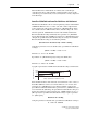
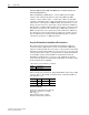
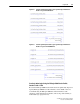
Regardless of the Datalink combination, Datalink x1 Out will always
contain the LSW and Datalink x2 Out will always contain the MSW. In the
following example, the PowerFlex 70 drive parameter 242 - [Power Up
Marker] contains a value of 88.4541 hours.
Conversion Example:
Parameter 242 - [Power Up Marker] = 88.4541 hours
MSW = 000D
hex
= 1101
binary
= 2
19
+ 2
18
+ 2
16
= 851968
LSW = 7F3D
hex
= 32573
Engineering Value = 851968 + 32573 = 884541
Parameter 242 Displayed Value = 88.4541 Hrs
Example Ladder Logic
Program Information
The example ladder logic programs in the sections of this chapter are
intended for and operate PowerFlex 7-Class drives.
Functions of the Example Programs
The example programs enable you to do the following:
• Receive Logic Status information from the drive.
• Send a Logic Command to control the drive (for example, start, stop).
• Send a Reference to the drive and receive Feedback from the drive.
• Send/receive Datalink data to/from the drive.
Logic Command/Status Words
These examples use the Logic Command word and Logic Status word for
PowerFlex 70/700 drives. Information for PowerFlex 750-Series drives has
been added to examples where applicable. See Appendix
D to view details.
The definition of the bits in these words may vary if you are using a
different DPI drive. See the documentation for your drive.
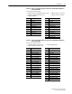
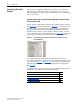
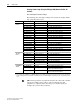
Datalink Word Parameter Data (Hex)
A2 Out MSW 242 000D
B1 Out LSW 242 7F3D