
User Manual

4-20 Configuring the I/O
20-COMM-C/Q ControlNet Adapter User Manual
Publication 20COMM-UM003F-EN-P
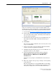
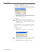
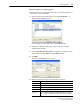
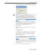
6. Under Connection Parameters, edit the following information.
Depending on the size of the drive’s Reference/Feedback and the number
of Datalinks used in your I/O configuration, Table 4.A
, Table 4.B, or
Table 4.C
defines the number of 16-bit words that you need to enter for
the Input Size and Output Size boxes.
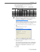
Table 4.A Drives with 16-bit Reference/Feedback and 16-bit Datalinks
These products include the following:
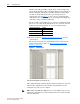
Table 4.B Drives with 16-bit Reference/Feedback and 32-bit Datalinks
These products include the following:
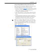
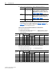
Box Assembly Instance Size
Input 1
(This value is required.)
The value will vary based on your application
(setting of Parameters 13 - [DPI I/O Cfg] and 26 -
[M-S Output]) and the size (16-bit or 32-bit) of the
Reference/Feedback and Datalinks in the drive. See
Table 4 .A
, Table 4.B or Table 4.C.
Output 2
(This value is required.)
The value will vary based on your application
(setting of Parameters 13 - [DPI I/O Cfg] and 25 -
[M-S Input]) and the size (16-bit or 32-bit) of the
Reference/Feedback and Datalinks in the drive. See
Table 4 .A
, Table 4.B or Table 4.C.
Configuration 6
(This value is required.)
0 (This value is required.)
• PowerFlex 70 drives with standard or enhanced control • SMC Flex smart motor controllers
• PowerFlex 700 drives with standard control • SMC-50 smart motor controllers
• PowerFlex 700H drives
Logic
Command/
Status
Ref/Fdbk
(16-bit)
Datalinks (16-bit) User Configured Settings
ABCD
Size in Words Par. 13 -
[DPI I/O Cfg]
Par. 25 -
[M-S Input]
Par. 26 -
[M-S Output]
Input Output
✔✔ 4 2 …0 0001 …0 0001 …0 0001
✔✔✔ 6 4 …0 0011 …0 0011 …0 0011
✔✔✔✔ 8 6 …0 0111 …0 0111 …0 0111
✔✔✔✔✔10 8 …0 1111 …0 1111 …0 1111
✔ ✔ ✔✔✔✔12 10 …1 1111 …1 1111 …1 1111
• PowerFlex 700 drives with vector control • PowerFlex Digital DC drives
• PowerFlex 700L drives with 700 control
Logic
Command/
Status
Ref/Fdbk
(16-bit)
Datalinks (32-bit) User Configured Settings
ABCD
Size in Words Par. 13 -
[DPI I/O Cfg]
Par. 25 -
[M-S Input]
Par. 26 -
[M-S Output]
Input Output
✔✔ 4 2 …0 0001 …0 0001 …0 0001
✔✔✔ 8 6 …0 0011 …0 0011 …0 0011
✔✔✔✔ 12 10 …0 0111 …0 0111 …0 0111
✔✔✔✔✔16 14 …0 1111 …0 1111 …0 1111
✔ ✔ ✔✔✔✔20 18 …1 1111 …1 1111 …1 1111