
User Manual

5-32 Using the I/O
20-COMM-C/Q ControlNet Adapter User Manual
Publication 20COMM-UM003F-EN-P
With any drive, you can use the controller data table addresses to directly
control and monitor the drive without creating any ladder logic program.
However, if you intend to use Human Machine Interface devices
(PanelView, and so forth) to operate the drive and view its status, you will
need to create descriptive controller data table addresses (Table 5.P
and
Table 5.Q
) and a ladder logic program that will pass that data to the data
table addresses used for messaging.
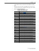
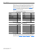
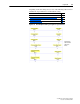
Table 5.P PLC-5 and Program Data Table Address Descriptions for Example Logic
Status/Feedback Ladder Logic Program
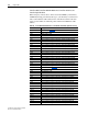
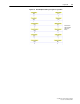
Table 5.Q Program and PLC-5 Data Table Address Descriptions for Example Logic
Command/Reference Ladder Logic Program
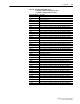
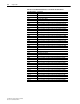
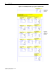
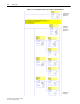
An example ladder logic program that uses these descriptive controller data
table addresses and passes their data to the descriptive program data table
addresses is shown in Figure 5.13
, Figure 5.14, Figure 5.15, and Figure 5.16.
Description
PLC-5 Data
Table Address
Description
Program Data
Table Address
Drive Ready N9:0/0 Status Ready B3:1/0
Drive Active N9:0/1 Status Active B3:1/1
Actual Direction (XIO) N9:0/3 Status Forward B3:1/3
Actual Direction (XIC) N9:0/3 Status Reverse B3:1/4
Drive Faulted N9:0/7 Status Faulted B3:1/7
Drive At Speed N9:0/8 Status At Speed B3:1/8
Speed Feedback (PowerFlex 70)
(PowerFlex 753/755)
N9:1
N9:2
Speed Feedback (PowerFlex 70)
(PowerFlex 753/755)
N20:1
F8:1
Description
Program Data
Table Address
Description
PLC-5 Data
Table Address
Command Stop B3:20/0 Drive Stop N10:0/0
Command Start B3:20/1 Drive Start N10:0/1
Command Jog B3:20/2 Drive Jog N10:0/2
Command Clear Faults B3:20/3 Drive Clear Faults N10:0/3
Command Forward Reverse (XIO) B3:20/4 Drive Forward N10:0/4
Command Forward Reverse (XIC) B3:20/4 Drive Reverse N10:0/5
Speed Reference (PowerFlex 70)
(PowerFlex 753/755)
N30:1
F8:3
Speed Reference (PowerFlex 70)
(PowerFlex 753/755)
N10:1
N10:2