PowerFlex ControlNet Adapters 20-COMM-C (Coax) Series A FRN 2.xxx, Series B FRN 3.xxx 20-COMM-Q (Fiber) Series A FRN 3.
Important User Information Solid state equipment has operational characteristics differing from those of electromechanical equipment. Safety Guidelines for the Application, Installation and Maintenance of Solid State Controls (Publication SGI-1.1 available from your local Rockwell Automation sales office or online at http:// www.rockwellautomation.com/literature) describes some important differences between solid state equipment and hard-wired electromechanical devices.
Summary of Changes The information below summarizes the changes made to this manual since its last release (August 2007). Description of Changes Page Reformatted document from half size (5.5 x 8.5 in.) to full size (8.5 x 11 in.) Throughout manual Added information about the Connected Components Workbench software configuration tool for drives and connected peripherals. Added information for use with PowerFlex 750-Series drives. Added information for use with PowerFlex Digital DC drives.
soc-ii Summary of Changes Notes: 20-COMM-C/Q ControlNet Adapter User Manual Publication 20COMM-UM003F-EN-P
Table of Contents Preface About This Manual Conventions Used in This Manual . . . . . . . . . . . . . . . . . . . . . . . . . . . . . . . . . . . . . . . . . . P-1 Rockwell Automation Support . . . . . . . . . . . . . . . . . . . . . . . . . . . . . . . . . . . . . . . . . . . . . P-2 Additional Resources . . . . . . . . . . . . . . . . . . . . . . . . . . . . . . . . . . . . . . . . . . . . . . . . . . . . P-2 Chapter 1 Getting Started Components. . . . . . . . . . . . . . . . . . . . . . . . . . . . .
ii Table of Contents Chapter 5 Using the I/O About I/O Messaging. . . . . . . . . . . . . . . . . . . . . . . . . . . . . . . . . . . . . . . . . . . . . . . . . . . . . 5-1 Understanding the I/O Image. . . . . . . . . . . . . . . . . . . . . . . . . . . . . . . . . . . . . . . . . . . . . . . 5-2 Using Logic Command/Status . . . . . . . . . . . . . . . . . . . . . . . . . . . . . . . . . . . . . . . . . . . . . . 5-8 Using Reference/Feedback . . . . . . . . . . . . . . . . . . . . . . . . . . . . . . .
Table of Contents Appendix C iii ControlNet Objects Identity Object. . . . . . . . . . . . . . . . . . . . . . . . . . . . . . . . . . . . . . . . . . . . . . . . . . . . . . . . . . C-2 Assembly Object . . . . . . . . . . . . . . . . . . . . . . . . . . . . . . . . . . . . . . . . . . . . . . . . . . . . . . . . C-3 Register Object . . . . . . . . . . . . . . . . . . . . . . . . . . . . . . . . . . . . . . . . . . . . . . . . . . . . . . . . . C-4 Parameter Object . . . . . . . . . . . . . . . . . . . .
iv Table of Contents Notes: 20-COMM-C/Q ControlNet Adapter User Manual Publication 20COMM-UM003F-EN-P
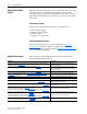
Preface About This Manual Topic Page Conventions Used in This Manual P-1 Rockwell Automation Support P-2 Additional Resources P-2 This manual provides information about the adapter and using it with PowerFlex 7-Class (Architecture-Class) drives. The adapter can be used with other products that support a DPI™ adapter, such as the DPI External Comms Kit (20-XCOMM-DC-BASE). See the documentation for your product for specific information about how it works with the adapter.
P-2 About This Manual Rockwell Automation Support Rockwell Automation offers support services worldwide, with over 75 sales and support offices, over 500 authorized distributors, and over 250 authorized systems integrators located through the United States alone. In addition, Rockwell Automation representatives are in every major country in the world. Local Product Support Contact your local Rockwell Automation, Inc.
About This Manual P-3 Resource Description PowerFlex 700S w/Phase I Control Installation Manual (Frames 1…6), publication 20D-IN024 PowerFlex 700S w/Phase I Control Installation Manual (Frames 9 and 10), publication PFLEX-IN006 PowerFlex 700S w/Phase I Control User Manual (All Frame Sizes), publication 20D-UM001 PowerFlex 700S w/Phase I Control Reference Manual, publication PFLEX-RM002 PowerFlex 700S w/Phase II Control Installation Manual (Frames 1…6), publication 20D-IN024 PowerFlex 700S w/Phase II Con
P-4 About This Manual Notes: 20-COMM-C/Q ControlNet Adapter User Manual Publication 20COMM-UM003F-EN-P
Chapter 1 Getting Started The adapter is intended for installation into a PowerFlex 7-Class drive and is used for network communication. The 20-COMM-C Series B coax adapter, firmware 2.xxx or later, or 20-COMM-Q Series A fiber adapter, firmware 2.xxx or later, can also be installed in an External DPI Comms Kit (20-XCOMM-DC-BASE). For PowerFlex 750-Series drives, we recommend using the 20-750-CNETC Coaxial ControlNet option module instead of the 20-COMM-C adapter.
1-2 Getting Started Features The features of the adapter include the following: • Typical mounting in a PowerFlex 7-Class drive. The 20-COMM-C Series B coax adapter, firmware 2.xxx or later, or 20-COMM-Q Series A fiber adapter, firmware 2.xxx or later, can also be installed in a DPI External Comms Kit and used with the kit’s optional I/O board. See Chapter 8, Using the Adapter in a DPI External Comms Kit (20-XCOMM-DC-BASE) for more information.
Getting Started Compatible Products 1-3 At the time of publication, the adapter is compatible with the following products: • PowerFlex 70 drives with standard or enhanced control • PowerFlex 750-Series drives (1) • PowerFlex 700 drives with standard or vector control • PowerFlex Digital DC drives • PowerFlex 700H drives • DPI External Comms Kit • PowerFlex 700S drives with Phase I or Phase II control • SMC™ Flex smart motor controllers • PowerFlex 700L drives with 700 vector control or 700S contr
1-4 Getting Started ❑ Drive and adapter configuration tool, such as the following: – PowerFlex 20-HIM-xx HIM – RSNetWorx for ControlNet software, version 6.00 or later – Connected Components Workbench software, version 1.02 or later Connected Components Workbench is the recommended stand-alone software tool for use with PowerFlex drives. You can obtain a free copy by: • Internet download at http://www.ab.com/support/abdrives/ webupdate/software.html • Requesting a DVD at http://www.ab.
Getting Started Safety Precautions 1-5 Please read the following safety precautions carefully. ! ! ! ! ! ! ! ATTENTION: Risk of injury or death exists. The PowerFlex drive may contain high voltages that can cause injury or death. Remove all power from the PowerFlex drive, and then verify power has been discharged before installing or removing an adapter. ATTENTION: Risk of injury or equipment damage exists.
1-6 Getting Started Quick Start This section is provided to help experienced users quickly start using the adapter. If you are unsure how to complete a step, refer to the referenced chapter. Step Action See 1 Review the safety precautions for the adapter. Throughout this manual 2 Verify that the PowerFlex drive is properly installed. Drive User Manual Install the adapter. b. Connect the adapter to the drive with the Internal Interface cable.
Chapter 2 Installing the Adapter This chapter provides instructions for installing the adapter in a PowerFlex 7-Class drive. The 20-COMM-C Series B coax adapter, firmware revision 2.xxx or later, or 20-COMM-Q Series A fiber adapter, firmware revision 2.xxx or later, can also be installed in a DPI External Comms Kit. In this case, see Chapter 8 or the 20-XCOMM-DC-BASE Installation Instructions, publication 20COMM-IN001, supplied with the kit.
2-2 Installing the Adapter Setting the Node Address Switches Set the adapter Node Address switches (Figure 2.1) by rotating the switches to the desired value for each digit. Important: Each node on the ControlNet network must have a unique address. Set the node address before power is applied because the adapter uses the node address it detects when it first receives power. To change a node address, you must set the new value and then remove and reapply power to (or reset) the adapter. Figure 2.
Installing the Adapter Connecting the Adapter to the Drive ! 2-3 ATTENTION: Risk of injury or death exists. The PowerFlex drive may contain high voltages that can cause injury or death. Remove power from the drive, and then verify power has been discharged before installing or removing the adapter. 1. Remove power from the drive. 2. Use static control precautions. 3. Remove the drive cover or open the drive door. 4.
2-4 Installing the Adapter Figure 2.2 DPI Ports and Internal Interface Cables 20-COMM-C (coaxial) Adapter shown ➊ ➋ PowerFlex 70 - All Frames ➌ ➍ PowerFlex 700 Frames 0 and 1 PowerFlex 700S Frames 0 and 1 PowerFlex 700 Frames 2 and Larger PowerFlex 700S Frames 2 through 6 HIM panel opens to allow access to DPI interface. To open panel, remove screws on left side of HIM panel and swing open.
Installing the Adapter Figure 2.3 2-5 Mounting and Grounding the Adapter Drive 0.9 N•m (8.0 lb•in) 4 Places Adapter Internal Interface Cable folded behind the adapter and in front of the drive. Ground Tab Detail PowerFlex 70 - All Frame Sizes (Adapter mounts in drive.) 0.9 N•m (8.0 lb•in) 4 Places PowerFlex 700 Frames 0 and 1 PowerFlex 700S Frames 0 and 1 (Adapter mounts on door.) Verify metal ground tab is bent 90° and is under the adapter before tightening screw.
2-6 Installing the Adapter Connecting the Adapter to the Network ! ATTENTION: Risk of injury or death exists. The PowerFlex drive may contain high voltages that can cause injury or death. Remove power from the drive, and then verify power has been discharged before installing or removing the adapter. 1. Remove power from the drive. 2. Use static control precautions. 3. Connect one end of a ControlNet cable to the network. See Figure 2.4 or Figure 2.5 for an example of wiring to a ControlNet network.
Installing the Adapter Applying Power ! 2-7 ATTENTION: Risk of equipment damage, injury, or death exists. Unpredictable operation may occur if you fail to verify that parameter settings are compatible with your application. Verify that settings are compatible with your application before applying power to the drive. Install the drive cover or close the drive door, and apply power to the drive. The adapter receives its power from the connected drive.
2-8 Installing the Adapter Table 2.A Drive and Adapter Start-Up Status Indicators Item Name Color State Description Drive STS Indicator ➊ STS (Status) Green Yellow Red Flashing Drive ready but not running, and no faults are present. Steady Drive running, no faults are present. Flashing, drive stopped An inhibit condition exists – the drive cannot be started. Check drive Parameter 214 - [Start Inhibits]. Flashing, drive running An intermittent type 1 alarm condition is occurring.
Installing the Adapter 2-9 2. If hard-wired discrete digital inputs are not used to control the drive, verify that unused digital input drive Parameters 361 - [Dig In1 Sel] and 362 - [Dig In2 Sel] are set to ‘0’ (Not Used). 3. Verify that drive Parameter 213 - [Speed Ref Source] is reporting that the source of the Reference to the drive is ‘22’ (DPI Port 5). This ensures that any Reference commanded from the network can be monitored by using drive Parameter 002 - [Commanded Speed].
2-10 Installing the Adapter Notes: 20-COMM-C/Q ControlNet Adapter User Manual Publication 20COMM-UM003F-EN-P
Chapter 3 Configuring the Adapter This chapter provides instructions and information for setting the parameters in the adapter.
3-2 Configuring the Adapter Using the PowerFlex 7-Class If your drive has either an LED or LCD HIM (Human Interface Module), it can be used to access parameters in the adapter as shown below. We HIM to Access Parameters recommend that you read through the steps for your HIM before performing the sequence. For additional information, see the drive documentation or the PowerFlex 7-Class HIM Quick Reference, publication 20HIM-QR001. Using an LED HIM Step Example Screens 1.
Configuring the Adapter Setting the Node Address 3-3 If the adapter Node Address switches (Figure 2.1) are set to ‘00’ (Program) the value of Parameter 03 - [CN Addr Cfg] determines the node address. When in any other combination of positions, the Node Address switches determine the node address. 1. Set the value of Parameter 03 - [CN Addr Cfg] to a unique node address. Default = 02 Port 5 Device 20-COMM-C Parameter #: 03 CN Addr Cfg 2 0 <> 63 2.
3-4 Configuring the Adapter 4. If you enabled one or more Datalinks, configure parameters in the drive to determine the source and destination of data in the Datalinks. When using Datalinks, up to 8 drive [Data In xx] parameters (300…307) and/or up to 8 [Data Out xx] parameters (310…317) must be assigned to point to the appropriate drive parameters for your application. See Chapter 4 for an example. 5. Reset the adapter (see Resetting the Adapter on page 3-7). The adapter is ready to receive I/O.
Configuring the Adapter 3-5 The adapter is ready to receive I/O from the master (that is, scanner). You must now configure the scanner to recognize and transmit I/O to the adapter. See Chapter 4, Configuring the I/O. Setting the Reference Adjustment A Reference Adjustment is a percent scaling factor for the Reference from the network. It can be set between 0.00…200.00% to allow the drive’s Reference to either match the network Reference (equal to 100.
3-6 Configuring the Adapter Changing the Fault Action Set the values of Parameters 10 - [Comm Flt Action] and 11 - [Idle Flt Action] to an action that meets your application requirements. Value Action Description 0 Fault The drive is faulted and stopped. (Default) 1 Stop The drive is stopped, but not faulted. 2 Zero Data The drive is sent ‘0’ values for data. This does not command a stop. 3 Hold Last The drive continues in its present state.
Configuring the Adapter Resetting the Adapter 3-7 Changes to switch settings and some adapter parameters require that you reset the adapter before the new settings take effect. You can reset the adapter by power cycling the drive or by using Parameter 09 - [Reset Module]. ! ATTENTION: Risk of injury or equipment damage exists. If the adapter is transmitting control I/O to the drive, the drive may fault when you reset the adapter.
3-8 Configuring the Adapter Updating the Adapter Firmware The adapter firmware can be updated over the network or serially through a direct connection from a computer to the drive using a 1203-USB or 1203-SSS serial converter. When updating firmware over the network, you can use the Allen-Bradley ControlFLASH software tool, the built-in update capability of DriveExplorer Lite or Full software, or the built-in update capability of DriveExecutive software.
Chapter 4 Configuring the I/O This chapter provides instructions on how to configure a Rockwell Automation ControlLogix, PLC-5, or SLC 500 controller to communicate with the adapter and connected PowerFlex drive.
4-2 Configuring the I/O The Configure Drivers screen reappears with the new driver in the Configured Drivers list. 7. Click Close to close the Configure Drivers screen. 8. Keep RSLinx running and verify that your computer recognizes the drive. a. Select Communications > RSWho. b. In the menu tree, click ‘+’ next to the ControlNet driver. ControlLogix Controller Example After the adapter is configured, the connected drive and adapter will be a single node on the network.
Configuring the I/O 4-3 Adding the Bridge to the I/O Configuration To establish communication between the controller and adapter over the network, you must first add the ControlLogix controller and its bridge to the I/O configuration. This procedure is similar for all RSLogix 5000 versions. 1. Start RSLogix 5000 software. 2. Select File > New to display the New Controller screen. a. Choose the appropriate choices for the fields in the screen to match your application. b. Click OK.
4-4 Configuring the I/O In this example, we use a 1756-CNB ControlNet Bridge (Series E), so the 1756-CNB option is selected. 5. Click CREATE. 6. In the Select Major Revision pop-up dialog box, select the major revision of its firmware. 7. Click OK. The bridge’s New Module screen appears. 8. Edit the following: Box Setting Name A name to identify the ControlNet bridge. Description Optional – description of the ControlNet bridge. Node The node address of the ControlNet bridge.
Configuring the I/O 4-5 There are three ways to add the adapter into the I/O configuration: • Drive Add-on Profiles (RSLogix 5000 software, version 16.00 or later) • Classic Profile (RSLogix 5000 software, versions 13.00…15.00) • Generic Profile (RSLogix 5000 software, all versions) These are described in separate sections below. If your version of RSLogix 5000 software supports drive Add-on Profiles, we recommend that you use this method. Using RSLogix 5000 Drive Add-on Profiles, Version 16.
4-6 Configuring the I/O In our example, we right-click on the 1756-CNB/E bridge. TIP: If the PowerFlex drive is not shown, go to http://www.ab.com/ support/abdrives/webupdate and download the latest RSLogix 5000 drive Add-on Profile. 2. From the list, select the drive and its connected adapter. For this example, we selected ‘PowerFlex 70 EC-C’. 3. Click CREATE. The drive’s New Module screen appears. 4. On the General tab, edit the following data about the drive/adapter.
Configuring the I/O 4-7 In this example, Datalinks are used to do the following. Read… Write to… Output Current (Parameter 3) Accel Time 1 (Parameter 140) DC Bus Voltage (Parameter 12) Decel Time 1 (Parameter 142) Fault 1 Code (Parameter 243) High Resolution Reference (Parameter 308) TIP: To get the latest RSLogix 5000 drive Add-on Profile, go to http:// www.ab.com/support/abdrives/webupdate. 6. In the Module Definition screen, edit the following information.
4-8 Configuring the I/O Box Setting Drive Rating The voltage and current rating of the drive. If the drive rating is not listed, the drive database is not installed on your computer. To get the correct drive rating, use the Create Database, Web Update, or Match Drive button described above. Connection Parameters via Datalinks. When selecting ‘Parameters via Datalinks’ (default), the controller tags for the Datalinks use the drive parameter names to which they are assigned.
Configuring the I/O 4-9 8. On the New Module screen, click the Connection tab. 9. In the ‘Requested Packet Interval (RPI)’ box, set the value to 5.0 milliseconds or greater. This value determines the maximum interval that a controller should use to move data to and from the adapter. To conserve bandwidth, use higher values for communicating with low priority devices. We recommend keeping the default value of 20.0 milliseconds.
4-10 Configuring the I/O 11. In the treeview, double-click Parameter List to display the drive’s linear parameter list. a. Scroll to drive parameter 90 - [Speed Ref A Sel] and set its value to ‘DPI Port 5’. This enables the drive to receive its Reference from the network via the 20-COMM-C or 20-COMM-Q adapter. For speed Reference scaling information, see Using Reference/Feedback on page 5-8. b. Click Close to save the setting and close the Parameters List screen. The New Module screen reappears. 12.
Configuring the I/O 4-11 Save the I/O Configuration to the Controller After adding the bridge and drive/adapter to the I/O configuration, you must download the configuration to the controller. You should also save the configuration to a file on your computer. 1. In the RSLogix 5000 window, select Communications > Download. The Download dialog box appears.
4-12 Configuring the I/O c. Click Save to save the configuration to a file on your computer. To be sure that the present project configuration values are saved, RSLogix 5000 software prompts you to upload them. Click Yes to upload and save the values. Correlate the Drive with the Controller You must now correlate the drive settings to the RSLogix 5000 project I/O settings so that they match. This requires loading the project I/O settings into the drive. 1.
Configuring the I/O 4-13 TIP: On subsequent connections to the drive (after initial download), click Upload. 7. When the Reset Comm Module screen appears, click Yes to reset the communication adapter so that the new I/O settings take effect. After resetting the communication module, which may take up to a minute to complete, a Comm Module Reset Error popup message may appear. If it does, click OK to close this message and complete the adapter reset. Then click OK to close the Drive Correlation screen. 8.
4-14 Configuring the I/O 5. Select Network > Online to display the Browse for Network screen. 6. Expand the communication path from your computer to the ControlNet bridge. The following screen shows our example navigating to devices that are on a ControlNet network. Depending on the communication link you are using, the navigation path may be different. 7. After selecting a valid path to the ControlNet network (for this example, A, ControlNet), click OK.
Configuring the I/O 4-15 If the icon for the drive (for this example, PowerFlex 70 EC) on the network appears as Unrecognized Device, you must download the EDS file for that PowerFlex drive from the Rockwell Automation website. a. Go to the website http://www.rockwellautomation.com/resources/eds. b. On the website search screen in the Network entry field, enter the type of network (for this example, ControlNet), which enables the use of the other search fields. c.
4-16 Configuring the I/O 8. Select Network > Enable Edits or check the Edits Enabled box in the RSNetWorx for ControlNet project window. If the bridge has a different I/O configuration than the configuration now being saved, the Online/Offline mismatch dialog box will appear. a. When both Options choices are available, click ‘Use offline data (download)’. When this choice is dimmed (grayed out), you must click ‘Use online data (upload)’. b. Click OK.
Configuring the I/O 4-17 Using the RSLogix 5000 Classic Profile, Versions 13.00…15.00 When compared to using the RSLogix 5000 Generic Profile (all versions), the RSLogix 5000 Classic Profile provides these advantages: • Profiles for specific drives (Figure 4.3) that provide descriptive controller tags for basic control I/O words (Logic Command/Status and Reference/ Feedback). The controller tags for Datalinks, however, have non-descriptive UserDefinedData[n] names.
4-18 Configuring the I/O When Datalinks are used, you must enable the desired Datalinks and assign names to their non-descriptive controller tags. When a Datalink is enabled, you must set the following adapter I/O parameters: • Parameter 13 - [DPI I/O Cfg] turns on the enabled Datalink bit so the 20-COMM-C or 20-COMM-Q adapter will communicate that Datalink’s information with the drive.
Configuring the I/O 4-19 Add the Drive/Adapter to the I/O Configuration To transmit data between the bridge and the drive, you must add the drive as a child device to the parent bridge. 1. In the treeview, right-click the bridge and select New Module… to display the Select Module screen. In our example, we right-click on the 1756-CNBR/D bridge. 2. Expand the Communications group to display all of the available communication modules. 3.
4-20 Configuring the I/O 6. Under Connection Parameters, edit the following information. Box Assembly Instance Size Input 1 The value will vary based on your application (This value is required.) (setting of Parameters 13 - [DPI I/O Cfg] and 26 [M-S Output]) and the size (16-bit or 32-bit) of the Reference/Feedback and Datalinks in the drive. See Table 4.A, Table 4.B or Table 4.C. Output 2 The value will vary based on your application (This value is required.
Configuring the I/O 4-21 Table 4.C Drives with 32-bit Reference/Feedback and 32-bit Datalinks These products include the following: • PowerFlex 700S drives with Phase I or Phase II control • PowerFlex 700L drives with 700S control Logic Command/ Status Ref/Fdbk (32-bit) Datalinks (32-bit) A B C ✔ ✔ ✔ ✔ ✔ ✔ ✔ ✔ ✔ ✔ ✔ ✔ ✔ ✔ ✔ ✔ ✔ ✔ D ✔ ✔ • PowerFlex 753 drives • PowerFlex 755 drives User Configured Settings Size in Words Par. 13 Par. 25 [DPI I/O Cfg] [M-S Input] Par.
4-22 Configuring the I/O The new node (‘My_PowerFlex_70_EC_Drive’ in this example) now appears under the bridge (‘My_ControlNet_Bridge’ in this example) in the I/O Configuration folder. If you double-click the Controller Tags, you will see that module-defined data types and tags have been automatically created (Figure 4.4). After you save and download the configuration, these tags allow you to access the Input and Output data of the drive via the controller’s ladder logic.
Configuring the I/O 4-23 1. In the RSLogix 5000 window, select Communications > Download. The Download dialog box appears. TIP: If a message box reports that RSLogix 5000 software is unable to go online, select Communications > Who Active to find your controller in the Who Active screen. After finding and selecting the controller, click Set Project Path to establish the path. If your controller does not appear, you need to add or configure the ControlNet driver with RSLinx software.
4-24 Configuring the I/O 6. Use the procedure in the subsection Use RSNetworx for ControlNet Software to Save the I/O to the Bridge on page 4-13 to: – Change the I/O Not Responding box in the upper-left of the RSLogix 5000 window from flashing green to steady green. – Remove the yellow warning symbols in the treeview under the I/O Configuration folder and drive profile. PLC-5 Controller Example After the adapter is configured, the connected drive and adapter will be a single node on the network.
Configuring the I/O 4-25 For this example, the adapter I/O parameters are set to these values. Adapter Parameter No. Setting 13 - [DPI I/O Cfg] xxxx xxxx xxx1 1111 25 - [M-S Input] xxxx xxxx xxx1 1111 26 - [M-S Output] xxxx xxxx xxx1 1111 2. Reset the adapter (see Resetting the Adapter on page 3-7) or power cycle the drive. For the drive speed reference and Datalink parameter values and the adapter setup parameter values, see Drive and Adapter Parameter Settings on page 5-24.
4-26 Configuring the I/O The following screen shows our example navigating to devices that are on a ControlNet network. Depending on the communication link you are using, the navigation path may be different. 7. After selecting a valid path to the ControlNet network (for this example, ControlNet, ControlNet), click OK. As the selected ControlNet path is browsed, RSNetWorx for ControlNet software creates a graph view window that shows a graphical representation of the devices on the network.
Configuring the I/O 4-27 b. On the website search screen in the Network entry field, enter the type of network (for this example, ControlNet), which enables the use of the other search fields. c. In the Keyword entry field, enter the type of PowerFlex drive (for this example, PowerFlex 70EC), noting that this field is space sensitive. d. Click Search. Due to the large number of EDS files, this search may take seconds or up to several minutes. e.
4-28 Configuring the I/O 9. In the RSNetWorx for ControlNet graph view window, right-click the PLC-5/40C icon and choose Scanlist Configuration to display the Scanlist Configuration screen. 10. Right-click the PowerFlex 70 EC drive row in the screen and choose Insert Connection… to display the Connection Properties screen. a. In this screen, leave the Connection Name box at the default value shown. b.
Configuring the I/O 4-29 Table 4.D Drives with 16-bit Reference/Feedback and 16-bit Datalinks These products include the following: • PowerFlex 70 drives with standard or enhanced control • PowerFlex 700 drives with standard control • PowerFlex 700H drives Logic Command/ Status Ref/Fdbk (16-bit) Datalinks (16-bit) A B C ✔ ✔ ✔ ✔ ✔ ✔ ✔ ✔ ✔ ✔ ✔ ✔ ✔ ✔ ✔ ✔ ✔ ✔ D ✔ ✔ • SMC Flex smart motor controllers • SMC-50 smart motor controllers User Configured Settings Size in Words Par. 13 Par.
4-30 Configuring the I/O An address row (in blue text) will be added below the PowerFlex 70 EC drive row. 12. Select File > Save to save the I/O configuration file to the PLC-5/40C controller. The Save Configuration dialog box appears. TIP: If both Save Type choices are available, we recommend to click ‘Optimize and re-write schedule for all connections’. 13. Click OK to download the I/O configuration to the controller. A warning will appear about communication and I/O disruption on the network. 14.
Configuring the I/O 4-31 Configuring Parameters for Network I/O Because the I/O for the drive is defined in the next subsection Use RSNetWorx for ControlNet Software to Configure the I/O and Save It to the 1747-SCNR Scanner on page 4-31, there is no need to configure any I/O inside the RSLogix 500 project, version 7.00 or later, until using the I/O as described in Chapter 5.
4-32 Configuring the I/O 5. Select Network > Online to display the Browse for Network screen. 6. Expand the communication path from your computer to the 1747-SCNR scanner. The following screen shows our example navigating to devices that are on a ControlNet network. Depending on the communication link you are using, the navigation path may be different. 7. After selecting a valid path to the ControlNet network (for this example, ControlNet, ControlNet), click OK.
Configuring the I/O 4-33 As the selected ControlNet path is browsed, RSNetWorx for ControlNet software creates a graph view window that shows a graphical representation of the devices on the network. If the icon for the drive (for this example, PowerFlex 70 EC) on the network appears as Unrecognized Device, you must download the EDS file for that PowerFlex drive from the Rockwell Automation website. a. Go to the website http://www.rockwellautomation.com/resources/ eds. b.
4-34 Configuring the I/O h. Reboot the computer and repeat steps 1 through 7 at the beginning of this subsection. The Unrecognized Device icon in the RSNetWorx for ControlNet graph view window in step 7 should have been replaced by a drive icon (for this example, the icon for a PowerFlex 70 EC drive). 8. Select Network > Enable Edits or check the Edits Enabled box in the RSNetWorx for ControlNet project window.
Configuring the I/O 4-35 10. Right-click the PowerFlex 70 EC drive row in the screen and select Insert Connection… to display the Connection Properties screen. a. In this screen, leave the Connection Name box at the default value shown. b. For the Requested Packet Interval box, choose a value that is suitable for your application, but is at least 5 ms. c. For the Input Size and Output Size boxes, use the pull-down menu to choose the number of words that are required for your I/O.
4-36 Configuring the I/O Table 4.H Drives with 16-bit Reference/Feedback and 32-bit Datalinks These products include the following: • PowerFlex 700 drives with vector control • PowerFlex 700L drives with 700 control Logic Command/ Status Ref/Fdbk (16-bit) Datalinks (32-bit) A B C ✔ ✔ ✔ ✔ ✔ ✔ ✔ ✔ ✔ ✔ ✔ ✔ ✔ ✔ ✔ ✔ ✔ ✔ Table 4.I D ✔ ✔ • PowerFlex Digital DC drives User Configured Settings Size in Words Par. 13 Par. 25 [DPI I/O Cfg] [M-S Input] Par.
Configuring the I/O 4-37 13. Click OK to download the I/O configuration to the scanner. A warning will appear about communication and I/O disruption on the network. 14. Click Yes. If this is the first time that you saved the project, the Save As dialog box appears. a. Navigate to a folder. b. Type a file name. c. Click Save to save the configuration as a file on your computer.
4-38 Configuring the I/O Notes: 20-COMM-C/Q ControlNet Adapter User Manual Publication 20COMM-UM003F-EN-P
Chapter 5 Using the I/O This chapter provides information and examples that explain how to control, configure, and monitor a PowerFlex 7-Class drive using the configured I/O.
5-2 Using the I/O Understanding the I/O Image The terms ‘input’ and ‘output’ are defined from the controller’s point of view. Therefore, output I/O is data that is produced by the controller and consumed by the adapter. Input I/O is status data that is produced by the adapter and consumed as input by the controller. The I/O image will vary based on the following: • Size (either 16-bit or 32-bit) of the Reference/Feedback words and Datalink words used by the drive.
Using the I/O 5-3 Table 5.
5-4 Using the I/O Table 5.
Using the I/O 5-5 Table 5.
5-6 Using the I/O Table 5.
Using the I/O 5-7 Table 5.
5-8 Using the I/O Table 5.
Using the I/O 5-9 When the Reference and Feedback are enabled, and a ControlLogix controller with a drive Add-on Profile or Classic Profile is used, specific controller tags are automatically created, sized (16-bit or 32-bit), and placed in the I/O image. PowerFlex 70/700/700H and PowerFlex 700L Drives with 700 Control The Reference/Feedback value is a scaled engineering value; it is not in Hertz or RPM. The Reference uses a ‘32767’ scale.
5-10 Using the I/O If parameter 82 - [Maximum Speed] is changed to 90 Hz, then: 90 Hz = 32767 Speed Feedback uses the same scaling as the speed Reference. TIP: For PowerFlex 700 drives with vector control, firmware 3.xxx or later, parameter 299 - [DPI Fdbk Select] enables you to select the feedback data coming from the drive over DPI. The default is ‘Speed Fdbk’ in Hz or RPM determined by parameter 079 - [Speed Units].
Using the I/O 5-11 PowerFlex Digital DC Drives The Reference/Feedback value is: 25000 = Maximum Reference Speed The maximum Reference speed is set using drive parameter 45 - [Max Ref Speed]. Using Datalinks A Datalink is a mechanism used by PowerFlex drives to transfer data to and from the controller. Datalinks allow a drive parameter value to be read or written without using an Explicit Message. When enabled, each Datalink occupies two 16-bit or 32-bit words in both the input and output image.
5-12 Using the I/O PowerFlex 700S, PowerFlex 700L with 700S Control, PowerFlex 753/755, and PowerFlex Digital DC Drives When using RSLogix 5000 software, version 16.00 or later, Datalink scaling is done automatically. However, when using RSLogix 5000 software, version 15.00 or earlier—or when using a PLC-5 or SLC 500 controller—Datalinks require scaling in the following way. Parameters are either 16-bit or 32-bit integers or REALs.
Using the I/O 5-13 Regardless of the Datalink combination, Datalink x1 Out will always contain the LSW and Datalink x2 Out will always contain the MSW. In the following example, the PowerFlex 70 drive parameter 242 - [Power Up Marker] contains a value of 88.4541 hours. Datalink Word Parameter Data (Hex) A2 Out MSW 242 000D B1 Out LSW 242 7F3D Conversion Example: Parameter 242 - [Power Up Marker] = 88.
5-14 Using the I/O ControlLogix Controller Example You can use any of RSLogix 5000 software versions to create the ladder logic. These are described in separate sections below. If your version of RSLogix 5000 software supports drive Add-on Profiles, we recommend that you use this method. Creating Ladder Logic Using the RSLogix 5000 Drive Add-on Profiles, Version 16.00 or Later Because the drive Add-on Profile automatically created descriptive controller tags (Figure 4.
Using the I/O Figure 5.2 ControlLogix Example Ladder Logic Program Using a Drive Add-on Profile for Logic Status/Feedback Figure 5.3 ControlLogix Example Ladder Logic Program Using a Drive Add-on Profile for Logic Command/Reference 5-15 Creating Ladder Logic Using the RSLogix 5000 Classic Profile, Versions 13.00…15.00 Because the RSLogix 5000 Classic Profile has been significantly improved upon by RSLogix 5000 drive Add-on Profiles, version 16.
5-16 Using the I/O Creating Ladder Logic Using the RSLogix 5000 Generic Profile, All Versions Drive and Adapter Parameter Settings The following drive and adapter settings were used for the example ladder logic program in this section.
Using the I/O 5-17 Controller Tags When you add the adapter and drive to the I/O configuration (Chapter 4), RSLogix 5000 software automatically creates generic (non-descriptive) controller tags for them. In this example program, the following controller tags are used. Figure 5.4 ControlLogix Controller Tags for Drive Generic Profile Example Ladder Logic Program You can expand the Input and Output tags to reveal the input and output configuration. Figure 5.
5-18 Using the I/O Figure 5.6 ControlLogix Output Image for Drive Generic Profile Example Ladder Logic Program PowerFlex 70 Drive 16-bit Speed Reference and Datalinks PowerFlex 750-Series Drive 32-bit Speed Reference and Datalinks Program Tags To use the Controller tags that are automatically created, you need to create the following Program tags for this example program. Figure 5.
Using the I/O 5-19 Depending on the drive being used, see one of the following subsections for information on speed Reference and Feedback scaling. Subsection Page PowerFlex 70/700/700H and PowerFlex 700L Drives with 700 Control 5-9 PowerFlex 700S and PowerFlex 700L Drives with 700S Control 5-10 PowerFlex 753/755 Drives 5-10 PowerFlex Digital DC Drives 5-11 Figure 5.
5-20 Using the I/O Figure 5.9 ControlLogix Example Ladder Logic Program Using a Drive Generic Profile for Logic Command/Reference PowerFlex 70 and PowerFlex 750-Series Drives PowerFlex 70 Drive Speed Reference PowerFlex 750-Series Drive Speed Reference Example Datalink Data The Datalink data used in the example program is shown in Figure 5.10.
Using the I/O 5-21 Figure 5.10 ControlLogix Example Datalinks for Ladder Logic Program Using a Drive Generic Profile PowerFlex 70 Drive PowerFlex 750-Series Drive For PowerFlex 7-Class drives, the scaling may need to be multiplied by 10 or 100, depending on the parameter. For more information, see Datalink Scaling on page 5-11.
5-22 Using the I/O TIP: When using a drive that has 16-bit Datalinks (PowerFlex 70, PowerFlex 700, and PowerFlex 700H drives) to transfer a 32-bit parameter, two contiguous drive Datalink parameters (for example, Data Out A1/A2, B1/B2, and so forth) are required. To determine if a parameter is a 32-bit parameter, see the Parameter section in the drive documentation and look for a 32 symbol in the ‘No.’ column. (All parameters in PowerFlex 700 Series B drives are 32-bit parameters.
Using the I/O PLC-5 Controller Example 5-23 Creating an RSLogix 5 Project, Version 7.00 or Later To transmit (read and write) data between the controller and drive, you must create discrete I/O instructions in the controller for Logic Command/Status, Reference/Feedback, and Datalinks. 1. Start RSLogix 5 software. The RSLogix 5 window appears. 2. Select File > New to display the Select Processor Type screen. 3. Assign a name for the processor. 4.
5-24 Using the I/O Drive and Adapter Parameter Settings The following drive and adapter settings were used for the example ladder logic program in this section.
Using the I/O 5-25 TIP: When using a drive that has 16-bit Datalinks (PowerFlex 70, PowerFlex 700, and PowerFlex 700H drives) to transfer a 32-bit parameter, two contiguous drive Datalink parameters (for example, Data Out A1/A2, B1/B2, and so forth) are required. To determine if a parameter is a 32-bit parameter, see the Parameter section in the drive documentation and look for a 32 symbol in the ‘No.’ column. (All parameters in PowerFlex 700 Series B drives are 32-bit parameters.
5-26 Using the I/O PowerFlex 70, PowerFlex 700 with Standard Control, and PowerFlex 700H Drives When using any of these products—which all contain INT (16-bit format) data types—you will read from and write to a single data table address in the controller. Table 5.
Using the I/O 5-27 PowerFlex 700 Drives with Vector Control and PowerFlex 700L Drives with 700 Control When using these drives, which contain DINT (32-bit format) data types, you will read from and write to the LSW data table address in the controller. Table 5.
5-28 Using the I/O PowerFlex 700S, PowerFlex 700L with 700S Control, PowerFlex 750-Series, and PowerFlex Digital DC Drives When using any of these drives, which contain both DINT (32-bit format) and REAL (floating point format) data types, you will always read from and write to the LSW data table address in the controller first. Then if the data value exceeds 16 bits, the remaining value will be in the MSW data table address. Table 5.
Using the I/O 5-29 Table 5.
5-30 Using the I/O Table 5.
Using the I/O 5-31 Table 5.
5-32 Using the I/O With any drive, you can use the controller data table addresses to directly control and monitor the drive without creating any ladder logic program. However, if you intend to use Human Machine Interface devices (PanelView, and so forth) to operate the drive and view its status, you will need to create descriptive controller data table addresses (Table 5.P and Table 5.Q) and a ladder logic program that will pass that data to the data table addresses used for messaging. Table 5.
Using the I/O 5-33 Figure 5.
5-34 Using the I/O Figure 5.
Using the I/O 5-35 Depending on the drive being used, see one of the following subsections for information on speed Reference and Feedback scaling. Subsection Page PowerFlex 70/700/700H and PowerFlex 700L Drives with 700 Control 5-9 PowerFlex 700S and PowerFlex 700L Drives with 700S Control 5-10 PowerFlex 753/755 Drives 5-10 PowerFlex Digital DC Drives 5-11 Figure 5.
5-36 Using the I/O Figure 5.16 PLC-5 Example Ladder Logic Program for Speed Reference PowerFlex 70 Drive Speed Reference PowerFlex 750-Series Drive Speed Reference (Continued on next page.
Using the I/O 5-37 (Continued from previous page.
5-38 Using the I/O SLC 500 Controller Example Creating an RSLogix 500 Project, Version 7.00 or Later To transmit (read and write) data between the controller and drive, you must create discrete I/O instructions in the controller for Logic Command/Status, Reference/Feedback, and Datalinks. Also, COP instructions must be included in the ladder logic program to convert the default memory addresses in Configuring the I/O (Chapter 4) to data table addresses. 1. Start RSLogix 500 software.
Using the I/O 5-39 7. In the project treeview, right-click IO Configuration and choose Open to display the I/O Configuration screen. 8. On the I/O Configuration screen, click Read IO Config. to display the Read IO Configuration from Online Processor screen. a. Click Who Active and select the communication path to the processor. b. Click OK. c. Click Read IO Config. to list the 1747-SCNR ControlNet Scanner Module. Note that the # column shows the slot number that the scanner occupies.
5-40 Using the I/O Drive and Adapter Parameter Settings The following drive and adapter settings were used for the example ladder logic program in this section.
Using the I/O 5-41 TIP: When using a drive that has 16-bit Datalinks (PowerFlex 70, PowerFlex 700, and PowerFlex 700H drives) to transfer a 32-bit parameter, two contiguous drive Datalink parameters (for example, Data Out A1/A2, B1/B2, and so forth) are required. To determine if a parameter is a 32-bit parameter, see the Parameter section in the drive documentation and look for a 32 symbol in the ‘No.’ column. (All parameters in PowerFlex 700 Series B drives are 32-bit parameters.
5-42 Using the I/O Figure 5.18 Data File Tables for Example Ladder Logic Program Depending on the drive, Table 5.R, Table 5.S, Table 5.T, Table 5.U, Table 5.V, or Table 5.W shows the I/O definitions as they relate to the N9:0 and N10:0 data table addresses in Figure 5.18 being used in this example.
Using the I/O 5-43 PowerFlex 700 Drives with Vector Control and PowerFlex 700L Drives with 700 Control When using any of these drives, which contain DINT (32-bit format) data types, you will read from and write to the LSW data table address in the controller. Table 5.
5-44 Using the I/O PowerFlex 700S, PowerFlex 700L with 700S Control, PowerFlex 750-Series, and PowerFlex Digital DC Drives When using any of these drives, which contain both DINT (32-bit format) and REAL (floating point format) data types, you will always read from and write to the LSW data table address in the controller first. Then if the data value exceeds 16 bits, the remaining value will be in the MSW data table address. Table 5.
Using the I/O 5-45 Table 5.
5-46 Using the I/O Table 5.
Using the I/O 5-47 Table 5.
5-48 Using the I/O To operate any drive and view its status using the data table addresses, Human Machine Interface devices (PanelView, and so forth), or a ladder logic program, you will need to create descriptive controller data table addresses (Table 5.X and Table 5.Y) and a ladder logic program that will pass the controller address data to the program data table addresses. Table 5.
Using the I/O 5-49 Figure 5.
5-50 Using the I/O Figure 5.
Using the I/O 5-51 Depending on the drive being used, see one of the following subsections for information on speed Reference and Feedback scaling. Subsection Page PowerFlex 70/700/700H and PowerFlex 700L Drives with 700 Control 5-9 PowerFlex 700S and PowerFlex 700L Drives with 700S Control 5-10 PowerFlex 753/755 Drives 5-10 PowerFlex Digital DC Drives 5-11 Figure 5.
5-52 Using the I/O Figure 5.22 SLC 500 Example Ladder Logic Program for Speed Reference PowerFlex 70 Drive Speed Reference PowerFlex 750-Series Drive Speed Reference (Continued on next page.
Using the I/O 5-53 (Continued from previous page.
5-54 Using the I/O Notes: 20-COMM-C/Q ControlNet Adapter User Manual Publication 20COMM-UM003F-EN-P
Chapter 6 Using Explicit Messaging This chapter provides information and examples that explain how to use Explicit Messaging to configure and monitor the adapter and connected PowerFlex 7-Class drive or PowerFlex 750-Series drive. Important: When used in a PowerFlex 750-Series drive, the 20-COMM-C or 20-COMM-Q adapter must have firmware 3.001 or later to support explicit messaging to drive parameters (Port 0). Furthermore, the adapter requires firmware 3.
6-2 Using Explicit Messaging About Explicit Messaging Explicit Messaging is used to transfer data that does not require continuous updates. With Explicit Messaging, you can configure and monitor a slave device’s parameters on the network. Important: When an explicit message is performed, by default no connection is made because it is an ‘unconnected’ message.
Using Explicit Messaging Performing Explicit Messages 6-3 There are five basic events in the Explicit Messaging process. The details of each step will vary depending on the type of controller being used. See the documentation for your controller. Important: There must be a request message and a response message for all Explicit Messages, whether you are reading or writing data. Figure 6.
6-4 Using Explicit Messaging ControlLogix Controller Examples TIP: To display the Message Configuration screen in RSLogix 5000 software, add a message instruction (MSG), create a new tag for the message (Properties: Base tag type, MESSAGE data type, controller scope), and click the button in the message instruction. For supported classes, instances, and attributes, see Appendix C, ControlNet Objects.
Using Explicit Messaging 6-5 ControlLogix Controller – Formatting a Message to Read a Single Parameter Using RSLogix 5000 Software, Version 15.00 or Later Figure 6.3 Parameter Read Single Message Configuration Screens The following table identifies the data that is required in each box to configure a message to read a single parameter. Configuration Tab Example Value Description Message Type Service Type (1) Service Code (1) Class Instance (2) Attribute Destination CIP Generic Parameter Read e (Hex.
6-6 Using Explicit Messaging ControlLogix Controller Example Ladder Logic Program to Read a Single Parameter Using RSLogix 5000 Software, Any Version A Get Attribute Single message is used to read a single parameter. This read message example reads the value of parameter 003 - [Output Current] in a PowerFlex 7-Class drive. Important: See Table 6.
Using Explicit Messaging 6-7 ControlLogix Controller – Formatting a Message to Read a Single Parameter Using RSLogix 5000 Software, Any Version Figure 6.5 Get Attribute Single Message Configuration Screens The following table identifies the data that is required in each box to configure a message to read a single parameter. Configuration Tab Example Value Description Message Type Service Type (1) Service Code (1) Class Instance (2) Attribute Destination CIP Generic Get Attribute Single e (Hex.
6-8 Using Explicit Messaging Write a Single Parameter ControlLogix Controller Example Ladder Logic Program to Write a Single Parameter Using RSLogix 5000 Software, Version 15.00 or Later A Parameter Write message is used to write to a single parameter. This write message example writes a value to parameter 140 - [Accel Time 1] in a PowerFlex 7-Class drive. Important: Parameter Object Class code 0x0F is not supported in PowerFlex 750-Series drives.
Using Explicit Messaging 6-9 ControlLogix Controller – Formatting a Message to Write a Single Parameter Using RSLogix 5000 Software, Version 15.00 or Later Figure 6.7 Parameter Write Single Message Configuration Screens The following table identifies the data that is required in each box to configure a message to write a single parameter.
6-10 Using Explicit Messaging ControlLogix Controller Example Ladder Logic Program to Write a Single Parameter Using RSLogix 5000 Software, Any Version A Set Attribute Single message is used to write to a single parameter. This write message example writes a value to parameter 140 - [Accel Time 1] in a PowerFlex 7-Class drive. Important: See Table 6.
Using Explicit Messaging 6-11 ControlLogix Controller – Formatting a Message to Write a Single Parameter Using RSLogix 5000 Software, Any Version Figure 6.9 Set Attribute Single Message Configuration Screens The following table identifies the data that is required in each box to configure a message to write a single parameter.
6-12 Using Explicit Messaging ControlLogix Controller – Explanation of Request and Response Data for Read/Write Multiple Messaging Using RSLogix 5000 Software, Any Version The data structures in Figure 6.10 and Figure 6.11 use 16-bit words and can accommodate up to 22 parameters in a single message. In the Response Message, a parameter number with the high bit set indicates that the associated parameter value field contains an error code (parameter number in response data will be negative).
Using Explicit Messaging 6-13 Read Multiple Parameters ControlLogix Controller Example Ladder Logic Program to Read Multiple Parameters Using RSLogix 5000 Software, Any Version A Scattered Read message is used to read the values of multiple parameters. Up to 22 parameters can be read. This read message example reads the values of these five parameters.
6-14 Using Explicit Messaging ControlLogix Controller – Formatting a Message to Read Multiple Parameters Using RSLogix 5000 Software, Any Version Figure 6.13 Scattered Read Message Configuration Screens The following table identifies the data that is required in each box to configure a message to read multiple parameters. Configuration Tab Example Value Description Message Type Service Type (1) Service Code (1) Class Instance Attribute Source Element CIP Generic Custom 4b (Hex.) 93 or 9F (Hex.
Using Explicit Messaging 6-15 ControlLogix Controller Example Scattered Read Request Data In this message example, we use the data structure in Figure 6.14 or Figure 6.15 in the source tag named Scattered_Read_Request to read these five parameters.
6-16 Using Explicit Messaging ControlLogix Controller Example Scattered Read Response Data The Scattered Read Request message reads the multiple parameters and returns their values to the destination tag (Scattered_Read_Response). Figure 6.16 or Figure 6.17 shows the parameter values. Figure 6.16 Example Scattered Read Response Data for PowerFlex 7-Class Drive In this message example, the parameters have the following values. PowerFlex 7-Class Drive Parameter Read Value 1 - [Output Freq] 32.
Using Explicit Messaging 6-17 Figure 6.18 Example Ladder Logic to Copy Response Data for PowerFlex 750-Series Drive In this message example, the parameters have the following values. PowerFlex 750-Series Drive Parameter Read Value Data Type 1 - [Output Freq] 45.0 Hz REAL 7 - [Output Current] 0.03 Amp REAL 137 - [Open Loop Fdbk] 1706253458 DINT 21581 - [Port 5: Analog Out 0 Data] 45.0 Hz REAL 260 - [Analog In0 Value] 9.
6-18 Using Explicit Messaging Write Multiple Parameters ControlLogix Controller Example Ladder Logic Program to Write Multiple Parameters Using RSLogix 5000 Software, Any Version A Scattered Write message is used to write to multiple parameters. This write message example writes the following values to these five parameters. PowerFlex 7-Class Drive Parameter Write Value PowerFlex 750-Series Drive Parameter Write Value 141 - [Accel Time 2] 11.1 Sec. 536 - [Accel Time 2] 11.1 Sec.
Using Explicit Messaging 6-19 ControlLogix Controller – Formatting a Message to Write Multiple Parameters Using RSLogix 5000 Software, Any Version Figure 6.20 Scattered Write Multiple Message Configuration Screens The following table identifies the data that is required in each box to configure a message to write multiple parameters. Configuration Tab Example Value Description Message Type Service Type (1) Service Code (1) Class Instance Attribute Source Element CIP Generic Custom 4c (Hex.
6-20 Using Explicit Messaging ControlLogix Controller Example Scattered Write Request Data In this message example, we use the data structure in Figure 6.21 or Figure 6.24 in the source tag (Scattered_Write_Request) to write new values to these parameters. PowerFlex 7-Class Drive Parameter Write Value PowerFlex 750-Series Drive Parameter Write Value Data Type 141 - [Accel Time 2] 11.1 Sec. 536 - [Accel Time 2] 11.1 Sec. REAL 143 - [Decel Time 2] 22.2 Sec. 538 - [Decel Time 2] 22.2 Sec.
Using Explicit Messaging 6-21 Figure 6.22 Example Scattered Write Response Data for PowerFlex 7-Class Drive The PowerFlex 750-Series drive uses 32-bit integer and REAL parameters. A COP command must be used to copy the 32-bit integer and REAL values to the Scattered_Write_Request integer array. Figure 6.23 shows the ladder logic used for this example. If the parameter data type is a REAL, then the source tag is a REAL. If the parameter data type is a 32-bit integer, then the source tag is a DINT.
6-22 Using Explicit Messaging Figure 6.24 Example Scattered Write Request Data for PowerFlex 750-Series Drive The results of the explicit message appear in the destination tag Scattered_Write_Response (Figure 6.25). Values of ‘0’ indicate no errors occurred. Figure 6.
Using Explicit Messaging PLC-5 Controller Examples 6-23 The ControlNet I/O Transfer (CIO) instruction is used to send explicit messages. For PLC-5/xxC controllers, Series F, revision B or earlier, the available services you should use are Get Attribute Single, Get Attribute All, Set Attribute Single, or Set Attribute All using a CIP Generic communication command.
6-24 Using Explicit Messaging PLC-5 Controller – Formatting a Message to Read a Single Parameter Figure 6.27 Read Single Message Configuration Screen The following table identifies the data that is required in each box to configure a message to read a single parameter. General Tab Example Value Description Communication Command Service Code Class Number Instance Number (1) Attribute Number PLC-5 Data Table Address CIP Generic e (Hex.) 93 or 9F (Hex.) (2) 3 (Hex.) 9 (Hex.
Using Explicit Messaging 6-25 PLC-5 Controller Example Single Read Response Data In this specific N40:0 message example, we use the data table address in Figure 6.28 to store the response value (0.13 amps) that was read from drive parameter 003 - [Output Current]. To determine the data type for the parameter and its required scaling, see the specific drive documentation. Figure 6.28 Example Single Read Response Data File Figure 6.
6-26 Using Explicit Messaging PLC-5 Controller Example Ladder Logic Program to Write a Single Parameter A write message is used to write to a single parameter. The specific N50:0 address shown in this write message example writes a value to parameter 140 - [Accel Time 1] in a PowerFlex 7-Class drive. Figure 6.
Using Explicit Messaging 6-27 PLC-5 Controller – Formatting a Message to Write a Single Parameter Figure 6.31 Write Single Message Configuration Screen The following table identifies the data that is required in each box to configure a message to write a single parameter. General Tab Example Value Description Communication Command Service Code Class Number Instance Number (1) Attribute Number (2) PLC-5 Data Table Address CIP Generic 10 (Hex.) 93 or 9F (Hex.) (3) 8c (Hex.) 9 or A (Hex.
6-28 Using Explicit Messaging PLC-5 Controller Example Single Write Response Data In this specific N50:0 message example, we use the data table address in Figure 6.32 to store the request value (10.0 sec.) that was written to drive parameter 140 - [Accel Time 1]. To determine the data type for the parameter and its required scaling, see the specific drive documentation. Figure 6.32 Example Single Write Response Data File Figure 6.
Using Explicit Messaging 6-29 PLC-5 Controller – Explanation of Request and Response Data for Read/Write Multiple Messaging The data structures in Figure 6.34 and Figure 6.35 use 16-bit words and can accommodate up to 22 parameters in a single message. In the Response Message, a parameter number with the high bit set indicates that the associated parameter value field contains an error code (parameter number in response data will be negative). Important: See Table 6.
6-30 Using Explicit Messaging PLC-5 Controller Example Ladder Logic Program to Read Multiple Parameters A Generic Bi-Directional scattered read message is used to read the values of multiple parameters. This read message example reads the values of these five parameters.
Using Explicit Messaging 6-31 PLC-5 Controller – Formatting a Message to Read Multiple Parameters Figure 6.37 Scattered Read Message Configuration Screens The following table identifies the data that is required in each box to configure a message to read multiple parameters. General Tab Example Value Description Communication Command Service Code Class Number Instance Number Attribute Number Snd Addr Generic Bi-Directional 4b (Hex.) 93 or 9F (Hex.) (1) 0 (Hex.
6-32 Using Explicit Messaging PLC-5 Controller Example Scattered Read Request Data In this message example, we use the data table addresses in Figure 6.38 or Figure 6.39 to store the request values to be read from these drive parameters.
Using Explicit Messaging 6-33 In this example, the parameters have the following values. PowerFlex 7-Class Drive Parameter Address Read Value 1 - [Output Freq] N70:1 90.0 Hz 3 - [Output Current] N70:4 0.09 Amp 6 - [Output Voltage] N70:7 229.1V AC 12 - [DC Bus Voltage] N70:10 325.3V DC 17 - [Analog In2 Value] N70:13 8.318 mA Figure 6.41 Example Scattered Read Response Data File for PowerFlex 750-Series Drive The PowerFlex 750-Series drive uses 32-bit integer and REAL parameters.
6-34 Using Explicit Messaging Figure 6.42 Example Ladder Logic to Copy Response Data for PowerFlex 750-Series Drive Parameter 137 [Open Loop Fdbk] PowerFlex 750-Series Drives Parameter 001 [Output Freq] In this message example, the parameters have the following values. 20-COMM-C/Q ControlNet Adapter User Manual Publication 20COMM-UM003F-EN-P PowerFlex 750-Series Drive Parameter Read Value Data Type 1 - [Output Freq] 45.0 Hz REAL 7 - [Output Current] 0.
Using Explicit Messaging 6-35 PLC-5 Controller Example Ladder Logic Program to Write Multiple Parameters A Generic Bi-Directional scattered write message is used to write to multiple parameters. This write message example writes the following values to these five parameters. PowerFlex 7-Class Drive Parameter Write Value PowerFlex 750-Series Drive Parameter Write Value 141 - [Accel Time 2] 11.1 Sec. 536 - [Accel Time 2] 11.1 Sec. 143 - [Decel Time 2] 22.2 Sec. 538 - [Decel Time 2] 22.2 Sec.
6-36 Using Explicit Messaging PLC-5 Controller – Formatting a Message to Write Multiple Parameters Figure 6.44 Scattered Write Multiple Message Configuration Screens The following table identifies the data that is required in each box to configure a message to write multiple parameters. General Tab Example Value Description Communication Command Service Code Class Number Instance Number Attribute Number Snd Addr Generic Bi-Directional 4c (Hex.) 93 or 9F (Hex.) (1) 0 (Hex.
Using Explicit Messaging 6-37 PLC-5 Controller Example Scattered Write Request Data In this message example, we use the data table addresses in Figure 6.45 or Figure 6.48 to store the request values to be written to these drive parameters. PowerFlex 7-Class Drive Parameter Address Write Value PowerFlex 750-Series Drive Parameter Write Value Data Type 141 - [Accel Time 2] N90:1 11.1 Sec. 536 - [Accel Time 2] 11.1 Sec. REAL 143 - [Decel Time 2] N90:4 22.2 Sec. 538 - [Decel Time 2] 22.2 Sec.
6-38 Using Explicit Messaging controller. If the parameter data type is a REAL, the floating point value in the PLC-5 controller is copied (COP) to two 16-bit integers. Then the MSW (most significant word) and LSW (least significant word) must be swapped before moving (MOV) the values to the array to be written to. See the drive documentation to determine the parameter data type (32-bit integer or REAL). Figure 6.
Using Explicit Messaging 6-39 Figure 6.48 Example Scattered Write Request Data File for PowerFlex 750-Series Drive The results of the explicit message appear in the destination tag array N80 (Figure 6.49). Values of ‘0’ indicate no errors occurred. Figure 6.
6-40 Using Explicit Messaging SLC 500 Controller Examples The CIP messaging method provides two ways to perform explicit messaging: • Read/Write Parameter Service simplifies setup by requiring less data to be entered in message configuration screens. However, the Read/Write Parameter Service can only be used to perform single parameter read or single parameter write explicit messages. (Multiple parameter reads or writes must be performed using the Generic Get/Set Attribute Service described below.
Using Explicit Messaging 6-41 SLC 500 Controller Explicit Messaging Using the Read/Write Parameter Service SLC 500 Controller Example Ladder Logic Program to Read a Single Parameter A Read Parameter message is used to read a single parameter. This read message example reads the value of parameter 003 - [Output Current] in a PowerFlex 7-Class drive. Important: Parameter Object Class code 0x0F is not supported in PowerFlex 750-Series drives.
6-42 Using Explicit Messaging SLC 500 Controller – Formatting a Message to Read a Single Parameter Using Read/Write Parameter Service Figure 6.51 Read Parameter Message Configuration Screen The following table identifies the data that is required in each box to configure a message to read a single parameter.
Using Explicit Messaging 6-43 SLC 500 Controller Example Read Single Response Data In this message example, we use the data table address in Figure 6.52 to store the response value (0.13 amps) that was read from drive parameter 003 - [Output Current]. To determine the data type for the parameter and its required scaling, see the specific drive documentation. Figure 6.52 Example Read Single Response Data File Figure 6.
6-44 Using Explicit Messaging SLC 500 Controller Example Ladder Logic Program to Write a Single Parameter Using Read/Write Parameter Service A Write Parameter message is used to write to a single parameter. This write message example writes a value to parameter 140 - [Accel Time 1] in a PowerFlex 7-Class drive. Important: Parameter Object Class code 0x0F is not supported in PowerFlex 750-Series drives.
Using Explicit Messaging 6-45 SLC 500 Controller – Formatting a Message to Write a Single Parameter Using Read/Write Parameter Service Figure 6.55 Write Parameter Message Configuration Screen The following table identifies the data that is required in each box to configure a message to write a single parameter.
6-46 Using Explicit Messaging SLC 500 Controller Example Write Single Request Data In this message example, we use the data table address in Figure 6.56 to store the request value (10.0 sec.) that was written to drive parameter 140 [Accel Time 1]. To determine the data type for the parameter and its required scaling, see the specific drive documentation. Figure 6.56 Example Write Single Request Data File Figure 6.
Using Explicit Messaging 6-47 SLC 500 Controller Explicit Messaging Using the Generic Get/Set Attribute Service SLC 500 Controller Example Ladder Logic Program to Read a Single Parameter A Generic Get Attribute Single message is used to read a single parameter. This read message example reads the value of parameter 003 - [Output Current] in a PowerFlex 7-Class drive. Important: See Table 6.
6-48 Using Explicit Messaging SLC 500 Controller – Formatting a Message to Read a Single Parameter Using Generic Get/Set Attribute Service Figure 6.59 Generic Get Attribute Single Message Configuration Screen The following table identifies the data that is required in each box to configure a message to read a single parameter.
Using Explicit Messaging 6-49 SLC 500 Controller Example Get Attribute Single Response Data In this message example, we use the data table address in Figure 6.60 to store the response value (0.13 amps) that was read from drive parameter 003 - [Output Current]. To determine the data type for the parameter and its required scaling, see the specific drive documentation. Figure 6.60 Example Get Attribute Single Response Data File Figure 6.
6-50 Using Explicit Messaging SLC 500 Controller Example Ladder Logic Program to Write a Single Parameter Using Generic Get/Set Attribute Service A Generic Set Attribute Single message is used to write to a single parameter. This write message example writes a value to parameter 140 [Accel Time 1] in a PowerFlex 7-Class drive. Important: See Table 6.
Using Explicit Messaging 6-51 SLC 500 Controller – Formatting a Message to Write a Single Parameter Using Generic Get/Set Attribute Service Figure 6.63 Generic Set Attribute Single Message Configuration Screen The following table identifies the data that is required in each box to configure a message to write a single parameter.
6-52 Using Explicit Messaging SLC 500 Controller Example Set Attribute Single Request Data In this message example, we use the data table address in Figure 6.64 to store the request value (10.0 sec.) that was written to drive parameter 140 [Accel Time 1]. To determine the data type for the parameter and its required scaling, see the specific drive documentation. Figure 6.64 Example Set Attribute Single Request Data File Figure 6.
Using Explicit Messaging 6-53 SLC 500 Controller – Explanation of Request and Response Data for Read/Write Multiple Messaging The data structures in Figure 6.66 and Figure 6.67 use 16-bit words and can accommodate up to 22 parameters in a single message. In the Response Message, a parameter number with the high bit set indicates that the associated parameter value field contains an error code (parameter number in response data will be negative). Important: See Table 6.
6-54 Using Explicit Messaging SLC 500 Controller Explicit Messaging Using the Generic Get/Set Attribute Service SLC 500 Controller Example Ladder Logic Program to Read Multiple Parameters A Custom scattered read message is used to read the values of multiple parameters. This read message example reads the values of these five parameters.
Using Explicit Messaging 6-55 SLC 500 Controller – Formatting a Message to Read Multiple Parameters Using Generic Get/Set Attribute Service Figure 6.69 Custom Scattered Read Message Configuration Screen The following table identifies the data that is required in each box to configure a message to read multiple parameters.
6-56 Using Explicit Messaging SLC 500 Controller Example Scattered Read Request Data In this message example, we use the data table addresses in Figure 6.70 or Figure 6.71 to store the request values to be read from these drive parameters.
Using Explicit Messaging 6-57 In this example, the parameters have the following values. PowerFlex 7-Class Drive Parameter Address Read Value 1 - [Output Freq] N70:1 90.0 Hz 3 - [Output Current] N70:4 0.09 Amp 6 - [Output Voltage] N70:7 229.1V AC 12 - [DC Bus Voltage] N70:10 325.3V DC 17 - [Analog In2 Value] N70:13 8.318 mA Figure 6.73 Example Scattered Read Response Data File for PowerFlex 750-Series Drive The PowerFlex 750-Series drive uses 32-bit integer and REAL parameters.
6-58 Using Explicit Messaging Figure 6.74 Example Ladder Logic to Copy Response Data for PowerFlex 750-Series Drive Parameter 137 [Open Loop Fdbk] PowerFlex 750-Series Drives Parameter 001 [Output Freq] In this message example, the parameters have the following values. 20-COMM-C/Q ControlNet Adapter User Manual Publication 20COMM-UM003F-EN-P PowerFlex 750-Series Drive Parameter Read Value Data Type 1 - [Output Freq] 45.0 Hz REAL 7 - [Output Current] 0.
Using Explicit Messaging 6-59 SLC 500 Controller Example Ladder Logic Program to Write Multiple Parameters Using Generic Get/Set Attribute Service A Custom scattered write message is used to write to multiple parameters. This write message example writes the following values to these five parameters. PowerFlex 7-Class Drive Parameter Write Value PowerFlex 750-Series Drive Parameter Write Value 141 - [Accel Time 2] 11.1 Sec. 536 - [Accel Time 2] 11.1 Sec. 143 - [Decel Time 2] 22.2 Sec.
6-60 Using Explicit Messaging SLC 500 Controller – Formatting a Message to Write Multiple Parameters Using Generic Get/Set Attribute Service Figure 6.76 Custom Scattered Write Multiple Message Configuration Screen The following table identifies the data that is required in each box to configure a message to write multiple parameters.
Using Explicit Messaging 6-61 SLC 500 Controller Example Scattered Write Request Data In this message example, we use the data table addresses in Figure 6.77 or Figure 6.80 to store the request values to be written to these drive parameters. PowerFlex 7-Class Drive Parameter Address Write Value PowerFlex 750-Series Drive Parameter Write Value Data Type 141 - [Accel Time 2] N90:1 11.1 Sec. 536 - [Accel Time 2] 11.1 Sec. REAL 143 - [Decel Time 2] N90:4 22.2 Sec. 538 - [Decel Time 2] 22.
6-62 Using Explicit Messaging controller. If the parameter data type is a REAL, the floating point value in the SLC 500 controller is copied (COP) to two 16-bit integers. Then the MSW (most significant word) and LSW (least significant word) must be swapped before moving (MOV) the values to the array to be written to. See the drive documentation to determine the parameter data type (32-bit integer or REAL). Figure 6.
Using Explicit Messaging 6-63 Figure 6.80 Example Scattered Write Request Data File for PowerFlex 750-Series Drive The results of the explicit message appear in the destination tag array N80 (Figure 6.81). Values of ‘0’ indicate no errors occurred. Figure 6.
6-64 Using Explicit Messaging Notes: 20-COMM-C/Q ControlNet Adapter User Manual Publication 20COMM-UM003F-EN-P
Chapter 7 Troubleshooting This chapter provides information for diagnosing and troubleshooting potential problems with the adapter and network. Understanding the Status Indicators Topic Page Understanding the Status Indicators 7-1 PORT Status Indicator 7-2 MOD Status Indicator 7-2 NET A and NET B Status Indicators 7-3 Viewing Adapter Diagnostic Items 7-4 Viewing and Clearing Events 7-6 The adapter has four status indicators. They can be viewed on the adapter or through the drive cover.
7-2 Troubleshooting PORT Status Indicator This red/green bicolor LED indicates the status of the adapter’s connection to the drive as shown in the table below. Status Cause Corrective Action Off The adapter is not powered or is not properly connected to the drive. • Securely connect the adapter to the drive using the Internal Interface (ribbon) cable. • Apply power to the drive (or adapter if mounted in a DPI External Comms Kit).
Troubleshooting NET A and NET B Status Indicators 7-3 These red/green bicolor LEDs indicate the status for the ControlNet Channel A and Channel B network connections as shown in the tables below. Depending on the state of these LEDs, they should be interpreted together or independently. Indicators Interpreted Together Status Cause Corrective Actions Both LEDs Off A reset occurred or the adapter is not powered. Apply power to the drive (or adapter if mounted in a DPI External Comms Kit) and network.
7-4 Troubleshooting Viewing Adapter Diagnostic If you encounter unexpected communications problems, the adapter’s diagnostic items may help you or Rockwell Automation personnel Items troubleshoot the problem. Adapter diagnostic items can be viewed with any of these drive configuration tools: • • • • LCD PowerFlex 7-Class HIM (Diagnostics/Device Items) Connected Components Workbench software, version 1.02 or later DriveExplorer software, version 2.01 or later DriveExecutive software, version 3.
Troubleshooting 7-5 Table 7.A Adapter Diagnostic Items (Continued) No. Name Description 15 Datalink A1 Out 16 Datalink A2 Out 17 Datalink B1 Out The present value of respective Datalink Out being received from the drive by this adapter. (If the drive indicates a 16-bit datalink size, the value appears in the least significant 16 bits of this diagnostic item, and the most significant 16 bits of this diagnostic item are zero.
7-6 Troubleshooting Viewing and Clearing Events The adapter has an event queue to record significant events that occur in the operation of the adapter. When such an event occurs, an entry is put into the event queue. You can view the event queue with any of these drive configuration tools: • • • • LCD PowerFlex 7-Class HIM Connected Components Workbench software, version 1.02 or later DriveExplorer software, version 2.01 or later DriveExecutive software, version 1.
Troubleshooting 7-7 Events Many events in the event queue occur under normal operation. If you encounter unexpected communications problems, the events may help you or Allen-Bradley personnel troubleshoot the problem. The following events may appear in the event queue. Table 7.B Adapter Events Code Event Description 1 No Event Empty event queue entry. 2 DPI Bus Off Flt A bus-off condition was detected on DPI. This event may be caused by loose or broken cables or by noise.
7-8 Troubleshooting Table 7.B Adapter Events (Continued) Code Event Description 39 OPT Close The adapter forced a fault condition on the I/O option of the DPI External Comms Kit. 40 OPT Timeout Communication between the adapter and I/O option of the DPI External Comms Kit was disrupted. 41 CN Link Up The adapter successfully joined the ControlNet network. 42 CN Link Down The adapter lost its connection to the ControlNet network.
Chapter 8 Using the Adapter in a DPI External Comms Kit (20-XCOMM-DC-BASE) This chapter provides information and examples that explain how to use the adapter in a DPI External Comms Kit (20-XCOMM-DC-BASE). The adapter is typically installed in the internal communication slot on the PowerFlex 7-Class drive.
8-2 Using the Adapter in a DPI External Comms Kit (20-XCOMM-DC-BASE) I/O Board Option (20-XCOMM-IO-OPT1) The I/O Board option, when installed in the DPI External Comms Kit, can be used with only a Series B adapter, firmware revision 3.xxx or later. The I/O Board provides six DC inputs and two Relay outputs for use by a controller on the network. Figure 8.
Using the Adapter in a DPI External Comms Kit (20-XCOMM-DC-BASE) 8-3 The data from the I/O Board is loaded into the Datalink word starting with bit 0 of Datalink D1 and concluding with bit 14. Bit 15 of Datalink D1 is reserved as an input valid Status flag. When the input data is valid, bit 15 = 1. For example, for the 20-XCOMM-IO-OPT1, the digital inputs and digital outputs are mapped as shown in Figure 8.4 and Figure 8.5 respectively. Figure 8.
8-4 Using the Adapter in a DPI External Comms Kit (20-XCOMM-DC-BASE) Viewing Optional I/O Diagnostic Items Viewing communication adapter diagnostic item 31 (OPT Status) shows the operating status of the optional I/O board. Bit State Status Indication Description 0 1 (On) OPT Present I/O data is being exchanged with the adapter. 1 1 (On) OPT Faulted The I/O board is taking its fault action. 2 1 (On) Hold Last Fault Action is ‘Hold Last’.
Appendix A Specifications This appendix presents the specifications for the adapter.
A-2 Specifications Environmental Regulatory Compliance Temperature Operating Storage -10…50 °C (14…122 °F) -40…85 °C (-40…185 °F) Relative Humidity 5…95% non-condensing Atmosphere Important: The adapter must not be installed in an area where the ambient atmosphere contains volatile or corrosive gas, vapors or dust. If the adapter is not going to be installed for a period of time, it must be stored in an area where it will not be exposed to a corrosive atmosphere.
Appendix B Adapter Parameters This appendix provides information about the adapter parameters. For configuration tools to monitor or change parameter values of the drive, adapter, and other connected peripherals, see Configuration Tools on page 3-1. Parameter List Parameter No. Name and Description Details 01 [DPI Port] Displays the port to which the adapter is connected. This will usually be port 5.
B-2 Adapter Parameters Parameter No. Name and Description Details 09 [Reset Module] Default: Values: No action if set to ‘0’ (Ready). Resets the adapter if set to ‘1’ (Reset Module). Restores the adapter to its factory default settings if set to ‘2’ (Set Defaults). This parameter is a command. It will be reset to ‘0’ (Ready) after the command has been performed. ! 10 ATTENTION: Risk of injury or equipment damage exists.
Adapter Parameters B-3 Parameter No. Name and Description Details 13 [DPI I/O Cfg] xxx0 0001 0 = I/O Disabled 1 = I/O Enabled Type: Read/Write Reset Required: Yes 15 [Flt Cfg Logic] Sets the Logic Command data that is sent to the drive if any of the following is true: • Parameter 10 - [Comm Flt Action] is set to ‘4’ (Send Flt Cfg) and I/O communication is disrupted.
B-4 Adapter Parameters Parameter No. Name and Description Details 25 [M-S Input] Default: Bit Values: Not Used Not Used Not Used Datalink D Input Datalink C Input Datalink B Input Datalink A Input Cmd/Ref x 6 x 5 0 4 0 3 0 2 0 1 1 0 27 [Ref Adjust] Sets the percent scale factor for the Reference received from the network.
Appendix C ControlNet Objects This appendix presents information about the ControlNet objects that can be accessed using Explicit Messages. For information on the format of Explicit Messages and example ladder logic programs, see Chapter 6, Using Explicit Messaging. Object Class Code Page Hex. Dec. Identity Object 0x01 1 C-2 Assembly Object 0x04 4 Register Object 0x07 7 Parameter Object (1) 0x0F Parameter Group Object (1) 0x10 Page Dec.
C-2 ControlNet Objects Identity Object Class Code Hexadecimal Decimal 0x01 1 Services Service Code 0x01 0x05 0x0E Implemented for: Class Instance Yes Yes Yes Yes Yes Yes Service Name Get_Attributes_All Reset Get_Attribute_Single Instances The number of instances depends on the number of components in the device connected to the adapter. This number of components can be read in Instance 0, Attribute 2.
ControlNet Objects Assembly Object C-3 Class Code Hexadecimal Decimal 0x04 4 Services Implemented for: Service Code Class Instance 0x0E Yes Yes 0x10 Yes Yes Service Name Get_Attribute_Single Set_Attribute_Single Instances Instance 1 2 Description All I/O data being read from the DPI device (read-only) All I/O data being written to the DPI device (read/write) Class Attributes Attribute ID 1 2 100 Access Rule Get Get Set Name Revision Max Instance Control Timeout Data Type WORD WORD WORD Descripti
C-4 ControlNet Objects Register Object Class Code Hexadecimal Decimal 0x07 7 Services Service Code Implemented for: Class Instance 0x0E Yes Yes 0x10 Yes Yes Service Name Get_Attribute_Single Set_Attribute_Single Instances Instance 1 2 3 4 5 6 7 8 9 10 11 12 13 14 15 16 17 18 (1) Description All I/O data being read from the DPI device (read-only) All I/O data written to the DPI device (read/write) Logic Status and Feedback data (read-only) Logic Command and Reference data (read/write) Datalink A (inpu
ControlNet Objects Parameter Object C-5 Class Code Hexadecimal Decimal 0x0F 15 Important: This object is not supported when the adapter is used with a PowerFlex 750-Series drive. Services Service Code Implemented for: Class Instance 0x01 Yes Yes 0x05 Yes No 0x0E Yes Yes 0x10 No Yes 0x4B No Yes Service Name Get_Attributes_All Reset Get_Attribute_Single Set_Attribute_Single Get_Enum_String Instances The number of instances depends on the number of parameters in the DPI drive.
C-6 ControlNet Objects Instance Attributes Attribute ID Access Rule Name (1) 1 Parameter Value 2 Get Link Path Size Data Type Description (2) (3) BYTE 0 = No link specified n = The size of Attribute 3 in bytes (4) 3 4 Get Get Link Path Descriptor WORD 5 Get Data Type BYTE 6 7 8 9 10 11 12 13 14 15 16 17 18 19 20 21 Get Get Get Get Get Get Get Get Get Get Get Get Get Get Get Get Data Size Parameter Name String Units String Help String Minimum Value Maximum Value Default Value Scaling Multi
ControlNet Objects Parameter Group Object C-7 Class Code Hexadecimal Decimal 0x10 16 Important: This object is not supported when the adapter is used with a PowerFlex 750-Series drive. Services Service Code Implemented for: Class Instance 0x01 Yes Yes 0x0E Yes Yes 0x10 Yes No Service Name Get_Attributes_All Get_Attribute_Single Set_Attribute_Single Instances The number of instances depends on the number of groups in the device.
C-8 ControlNet Objects PCCC Object Class Code Hexadecimal Decimal 0x67 103 Services Service Code Implemented for: Class Instance 0x4B No Yes 0x4C No Yes Service Name Execute_PCCC Execute_DH+ Instances Not supported. Class Attributes Not supported. Instance Attributes Not supported.
ControlNet Objects C-9 Message Structure for Execute_DH+ Request Name DLink DSta DUser SLink SSta SUser CMD STS TNSW FNC PCCC_ params Data Type UINT USINT USINT UINT USINT USINT USINT USINT UINT USINT ARRAY of USINT Description Destination Link ID Destination Station number Destination “User” number Source Link ID Source Station number Source User number Command byte 0 Transport word Function code; not used for all CMDs CMD/FNC specific parameters Response Name DLink DSta DUser SLink SSta SUser CMD STS
C-10 ControlNet Objects N-Files N-File N41 Description This N-file lets you read and write control I/O messages. You can write control I/O messages only when all of the following conditions are true: • The adapter is not receiving I/O from a scanner. For example, there is no scanner on the network, the scanner is in idle (program) mode, the scanner is faulted, or the adapter is not mapped to the scanner. • The adapter is not receiving peer I/O from another adapter.
ControlNet Objects N45 C-11 This N-file lets you read and write control I/O messages. You can write control I/O messages only when all of the following conditions are true: • The adapter is not receiving I/O from a scanner. For example, there is no scanner on the network, the scanner is in idle (program) mode, the scanner is faulted, or the adapter is not mapped to the scanner. • The adapter is not receiving peer I/O from another adapter.
C-12 ControlNet Objects N-File N201…N212 Description These N-files let you read and write values to DPI and Host parameters in Ports 1…14 (for example, a HIM or adapter) as 32-bit double words. You can interpret the data in various ways (for example, 32-bit real, 32-bit integer) To read a parameter, you need to send a message with two elements. For example, to read parameter 1 in the peripheral connected to DPI port 1, read two elements beginning at N201:2.
ControlNet Objects DPI Device Object C-13 Class Code Hexadecimal Decimal 0x92 146 Services Service Code Implemented for: Class Instance 0x0E Yes Yes 0x10 Yes Yes Service Name Get_Attribute_Single Set_Attribute_Single Instances The number of instances depends on the number of components in the device. The total number of components can be read in Instance 0, Class Attribute 4.
C-14 ControlNet Objects Attribute ID Access Rule Name 2 Set Language Code Data Type BYTE 3 Get Product Series BYTE 4 Get Number of Components BYTE 5 6 7 8 9 11 12 13 Set Get Get Get Get Get Get Get User Definable Text Status Text Configuration Code Configuration Text Brand Code NVS Checksum Class Revision Character Set Code STRING[16] STRING[12] BYTE STRING[16] WORD WORD WORD BYTE 15 Get Languages Supported 18 19 Get Set Serial Number Language Selected STRUCT of: BYTE BYTE[n] STRUCT of
ControlNet Objects Attribute ID Access Rule Name 34 Get Key Information 35 39 128 129 130 Get Get Get Get Get NVS CRC SI Driver Code Customization Code Customization Revision Number Customization Device Text Data Type STRUCT of: DWORD DWORD WORD WORD WORD BYTE BYTE BYTE BYTE BYTE BYTE[16] DWORD WORD WORD WORD STRING[32] C-15 Description Rating Code Device Serial Number Customization Code Customization Revision Brand Code Family Code Config Code Language Code Major Revision Minor Revision Customer-Gen
C-16 ControlNet Objects DPI Parameter Object Class Code Hexadecimal Decimal 0x93 147 To access ‘Host Config’ parameters, use the HOST DPI Parameter Object (Class code 0x9F). Instances The number of instances depends on the number of parameters in the device. The total number of parameters can be read in Instance 0, Attribute 0.
ControlNet Objects C-17 Instance Attributes Attribute ID 6 8 9 10 Get Get/Set Get/Set DPI Descriptor DPI Parameter Value DPI RAM Parameter Value Data Type STRUCT of: BOOL[32] CONTAINER CONTAINER CONTAINER STRING[16] STRING[4] WORD WORD WORD WORD WORD WORD WORD BYTE BYTE WORD WORD CONTAINER WORD WORD WORD INT STRUCT of: BOOL[32] CONTAINER(1) CONTAINER CONTAINER CONTAINER WORD WORD STRING[4] UINT UINT UINT INT BYTE[3] BYTE STRING[16] BOOL[32] Various Various 11 Get/Set DPI Link BYTE[3] 12 13 Get G
C-18 ControlNet Objects Attribute ID 18 19 20 21 22 (1) (2) (3) Access Rule Get Get Get Get Get Name International DPI Offline Parameter Text International DPI Online Parameter Text International DPI Online Read Full DPI Extended Descriptor International DPI Offline Read Full Data Type STRUCT of: STRINGN STRINGN STRUCT of: STRINGN STRINGN STRUCT of: BOOL[32] CONTAINER CONTAINER CONTAINER CONTAINER WORD WORD WORD WORD WORD INT BYTE[3] BYTE BOOL[32] STRINGN STRINGN DWORD STRUCT of: BOOL CONTAINER
ControlNet Objects C-19 Descriptor Attributes Bit 0 1 2 Name Data Type (Bit 1) Data Type (Bit 2) Data Type (Bit 3) 3 Sign Type 4 Hidden 5 Not a Link Sink 6 Not Recallable 7 ENUM 8 Writable 9 Not Writable When Enabled 10 Instance 11 Uses Bit ENUM Mask 12 13 14 15 16 17 18 Decimal Place (Bit 0) Decimal Place (Bit 1) Decimal Place (Bit 2) Decimal Place (Bit 3) Extended Data Type (Bit 1) Extended Data Type (Bit 2) Extended Data Type (Bit 3) 19 20 21 22 23 24 25 26 Parameter Exists Not U
C-20 ControlNet Objects Extended Descriptor Attributes Bit 0 Name Indirect Mode 1 2 3 4 5 6 7 8 9 10 11 12 13 14 15 16 17 18 19 20 Indirect Type 0 Indirect Type 1 Indirect Type 2 Indirect Type 3 Indirect Type 4 Indirect Type 5 Indirect Type 6 Indirect Type 7 Indirect Type 8 Indirect Type 9 Indirect Type 10 Indirect Type 11 Indirect Type 12 Indirect Type 13 Indirect Type 14 FP Max Decimals Bit 0 FP Max Decimals Bit 1 FP Max Decimals Bit 2 FP Max Decimals Bit 1 Extended Parameter Reference 21 22 23 2
ControlNet Objects Bit 27 Name Command Parameter 28 Current Value Is Default 29 Use Zero Text 30-31 Reserved C-21 Description This parameter commands the drive to take an action, such as ‘Reset Defaults’ or ‘Autotune’, and then returns to a value of zero. Offline software tools will not allow setting this parameter to anything other than a value of zero. If an offline file contains a Command Parameter with a non-zero value, the offline software tool will change the value to zero.
C-22 ControlNet Objects DPI Fault Object Class Code Hexadecimal Decimal 0x97 151 Products such as PowerFlex drives use this object for faults. Adapters use this object for events. Services Service Code Implemented for: Class Instance 0x0E Yes Yes 0x10 Yes Yes Service Name Get_Attribute_Single Set_Attribute_Single Instances The number of instances depends on the maximum number of faults or events supported in the queue. The maximum number of faults/events can be read in Instance 0, Attribute 2.
ControlNet Objects Attribute ID 5 Access Rule Get Name Fault Data List 6 Get Number of Recorded Faults Data Type STRUCT of: BYTE BYTE WORD[n] WORD 7 Get Fault Parameter Reference WORD C-23 Description Number of faults/events in the queue. A ‘0’ indicates the fault queue is empty. Number of faults/events in the queue. A ‘0’ indicates the fault queue is empty. Number of faults/events in the queue. A ‘0’ indicates the fault queue is empty.
C-24 ControlNet Objects DPI Alarm Object Class Code Hexadecimal Decimal 0x98 152 Products such as PowerFlex drives use this object for alarms or warnings. Adapters do not support this object. Services Service Code Implemented for: Class Instance 0x0E Yes Yes 0x10 Yes No Service Name Get_Attribute_Single Set_Attribute_Single Instances Example 0 1 2 Description Class Attributes (Drive) Most Recent Alarm Second Most Recent Alarm … Instances (Hex.) (Dec.
ControlNet Objects C-25 Instance Attributes Attribute ID 0 1 2 Access Rule Get Get Get Name Full/All Information Basic Information International Alarm Text Data Type STRUCT of WORD STRUCT of: BYTE BYTE STRING[16] STRUCT of: LWORD BOOL[16] WORD CONTAINER[n] STRUCT of WORD STRUCT of: BYTE BYTE STRUCT of: LWORD BOOL[16] STRINGN Description Alarm code Alarm source DPI port DPI Device Object Alarm text Alarm time stamp Timer value (0 = timer not supported) BOOL[0]: (0 = invalid data, 1 = valid data)
C-26 ControlNet Objects DPI Diagnostic Object Class Code Hexadecimal Decimal 0x99 153 Services Service Code Implemented for: Class Instance 0x0E Yes Yes 0x10 Yes Yes Service Name Get_Attribute_Single Set_Attribute_Single Instances The number of instances depends on the maximum number of diagnostic items in the device. The total number of diagnostic items can be read in Instance 0, Attribute 2.
ControlNet Objects C-27 Instance Attributes Attribute ID Access Rule Name 0 Get Full/All Information 1 2 3 (1) (2) Get/Set Get Get Value International Diagnostic Item Text International Full Read All Data Type STRUCT of: BOOL[32] CONTAINER (1) CONTAINER CONTAINER CONTAINER WORD WORD STRING[4] UINT UINT UINT INT DWORD STRING[16] Various STRUCT of: STRINGN STRINGN STRUCT of: BOOL[32] CONTAINER CONTAINER CONTAINER CONTAINER WORD WORD WORD WORD WORD INT DWORD BOOL[32] STRINGN STRINGN Description Desc
C-28 ControlNet Objects DPI Time Object Class Code Hexadecimal Decimal 0x9B 155 Services Service Code Implemented for: Class Instance 0x0E Yes Yes 0x10 Yes Yes Service Name Get_Attribute_Single Set_Attribute_Single Instances The number of instances depends on the number of timers in the device. Instance 1 is always reserved for a real-time clock although a device may not support it. The total number of timers can be read in Instance 0, Attribute 2.
ControlNet Objects Attribute ID Access Rule 8 Get 9 Get/Set Name Active Time Zone Data Custom Time Zone Data Data Type STRUCT of: INT BYTE BYTE BYTE BYTE BYTE BYTE INT BYTE BYTE BYTE BYTE BYTE BYTE STRUCT of: INT BYTE BYTE BYTE BYTE BYTE BYTE INT BYTE BYTE BYTE BYTE BYTE BYTE C-29 Description Standard bias Standard month Standard day of week Standard week Standard hour Standard minute Standard second Daylight offset Daylight month Daylight day of week Daylight week Daylight hour Daylight minute Dayl
C-30 ControlNet Objects Host DPI Parameter Object Class Code Hexadecimal 0x9F Decimal 159 To access ‘Device’ parameters, use the DPI Parameter Object (Class Code 0x93). Important: The Host DPI Parameter Object is supported only when the adapter is used with a PowerFlex 750-Series drive. Instances The number of instances depends on the number of parameters in the device. The total number of parameters can be read in Instance 0, Attribute 0.
ControlNet Objects C-31 Instance Attributes Attribute ID 6 8 9 10 Get Get/Set Get/Set DPI Descriptor DPI Parameter Value DPI RAM Parameter Value Data Type STRUCT of: BOOL[32] CONTAINER CONTAINER CONTAINER STRING[16] STRING[4] WORD WORD WORD WORD WORD WORD WORD BYTE BYTE WORD WORD CONTAINER WORD WORD WORD INT STRUCT of: BOOL[32] CONTAINER(1) CONTAINER CONTAINER CONTAINER WORD WORD STRING[4] WORD WORD WORD INT BYTE[3] BYTE STRING[16] BOOL[32] Various Various 11 Get/Set DPI Link BYTE[3] 12 13 Get G
C-32 ControlNet Objects Attribute ID 18 19 20 21 22 (1) (2) (3) Access Rule Name Get International DPI Offline Parameter Text Get Get Get Get International DPI Online Parameter Text International DPI Online Read Full DPI Extended Descriptor International DPI Offline Read Full Data Type Struct of: STRINGN STRINGN Struct of: STRINGN STRINGN Struct of: BOOL[32] CONTAINER CONTAINER CONTAINER CONTAINER WORD WORD WORD WORD WORD INT BYTE[3] BYTE BOOL[32] STRINGN STRINGN UDINT Struct of: BOOL CONTAINE
ControlNet Objects C-33 Descriptor Attributes Bit 0 1 2 3 4 5 6 7 8 9 10 11 12 13 14 15 16 17 18 19 20 21 22 23 24 25 26 27 28 29 30 31 Name Data Type (Bit 1) Data Type (Bit 2) Data Type (Bit 3) Description Right bit is least significant bit (0).
C-34 ControlNet Objects Extended Descriptor Attributes Bit 0 Name Indirect Mode 1 2 3 4 5 6 7 8 9 10 11 12 13 14 15 16 17 18 19 20 Indirect Type 0 Indirect Type 1 Indirect Type 2 Indirect Type 3 Indirect Type 4 Indirect Type 5 Indirect Type 6 Indirect Type 7 Indirect Type 8 Indirect Type 9 Indirect Type 10 Indirect Type 11 Indirect Type 12 Indirect Type 13 Indirect Type 14 FP Max Decimals Bit 0 FP Max Decimals Bit 1 FP Max Decimals Bit 2 FP Max Decimals Bit 1 Extended Parameter Reference 21 22 23 2
ControlNet Objects Bit 27 Name Command Parameter 28 Current Value Is Default 29 Use Zero Text 30-31 Reserved C-35 Description This parameter commands the drive to take an action, such as ‘Reset Defaults’ or ‘Autotune’, and then returns to a value of zero. Offline software tools will not allow setting this parameter to anything other than a value of zero. If an offline file contains a Command Parameter with a non-zero value, the offline software tool will change the value to zero.
C-36 ControlNet Objects Notes: 20-COMM-C/Q ControlNet Adapter User Manual Publication 20COMM-UM003F-EN-P
Appendix D Logic Command/Status Words This appendix presents the definitions of the Logic Command and Logic Status words that are used for some products that can be connected to the adapter. If the Logic Command/Logic Status for the product that you are using is not listed, refer to your product’s documentation.
D-2 Logic Command/Status Words Logic Status Word Logic Bits 15 14 13 12 11 10 9 8 7 6 5 4 3 2 1 x x x x x x x x x x (1) x x x x x See ‘Owners’ in drive User Manual for further information. 20-COMM-C/Q ControlNet Adapter User Manual Publication 20COMM-UM003F-EN-P 0 x Status Ready Active Command Direction Actual Direction Accel Decel Alarm Fault At Speed Local Control (1) Reference Description 0 = Not Ready (Par.
Logic Command/Status Words PowerFlex 700S (Phase II Control) and 700L (with 700S Control) Drives D-3 Logic Command Word Logic Bits 15 14 13 12 11 10 9 8 7 6 5 4 3 2 1 x x x x x x x x x x x x x x x 0 x Command Normal Stop Start (1) Jog 1 Clear Fault (2) Unipolar Direction Description 0 = Not Normal Stop 1 = Normal Stop 0 = Not Start 1 = Start 0 = Not Jog using [Jog Speed 1] (Par. 29) 1 = Jog using [Jog Speed 1] (Par.
D-4 Logic Command/Status Words Logic Status Word Logic Bits 15 14 13 12 11 10 9 8 7 6 5 4 3 2 1 x x x x x x x x x x x x x x x (1) 0 x Status Active Running Command Direction Actual Direction Accel Decel Jogging Fault Alarm Flash Mode Run Ready At Limit (1) Tach Loss Sw At Zero Spd At Setpt Spd Enable Description 0 = Not Active 1 = Active 0 = Not Running 1 = Running 0 = Reverse 1 = Forward 0 = Reverse 1 = Forward 0 = Not Accelerating 1 = Accelerating 0 = Not Decelerating 1 = Decelerating 0 = No
Logic Command/Status Words D-5 PowerFlex 750-Series Drives Important: When using a 20-COMM-C or 20-COMM-Q adapter with a PowerFlex 750-Series drive, the upper word (bits 16…31) of the Logic Command and Logic Status words are not accessible and cannot be used. Only when using a PowerFlex 750-Series drive with a 20-750 communication Option Module, or the PowerFlex 755 drive’s embedded EtherNet/IP adapter, is the upper word accessible and used.
D-6 Logic Command/Status Words Logic Status Word Logic Bits 31…15 14 13 12 11 10 9 8 7 6 5 4 3 2 1 x x x x x x x x x x x x x x x 20-COMM-C/Q ControlNet Adapter User Manual Publication 20COMM-UM003F-EN-P 0 Command x Run Ready Active Command Direction Actual Direction Accelerating Decelerating Alarm Fault At Setpt Spd Manual Spd Ref ID 0 Spd Ref ID 1 Spd Ref ID 2 Spd Ref ID 3 Spd Ref ID 4 Reserved Description 0 = Not Ready to Run (Par.
Logic Command/Status Words D-7 PowerFlex Digital DC Drives Logic Command Word Logic Bits 15 14 13 12 11 10 9 8 7 6 5 4 3 2 1 x x x x x x x x x x x x x x x 0 x Command Stop (1) Start (1)(2) Jog Clear Faults Direction Local Control MOP Increment Accel Rate Decel Rate Reference Select (3) MOP Decrement Description 0 = Not Stop 1 = Stop 0 = Not Start 1 = Start 0 = Not Jog (Par.
D-8 Logic Command/Status Words Logic Status Word Logic Bits 15 14 13 12 11 10 9 8 7 6 5 4 3 2 1 x x x x x x x x x x (1) x x x x x See ‘Owners’ in drive User Manual for further information. 20-COMM-C/Q ControlNet Adapter User Manual Publication 20COMM-UM003F-EN-P 0 x Status Ready Description 0 = Not Ready (Par.
Glossary A Adapter Devices such as drives, controllers, and computers usually require a network communication adapter to provide a communication interface between them and a network such as ControlNet. An adapter reads data on the network and transmits it to the connected device. It also reads data in the device and transmits it to the network. The 20-COMM-C (coax) or 20-COMM-Q (fiber) ControlNet adapter connects PowerFlex 7-Class drives to a ControlNet network.
G-2 Glossary Controller A controller, also called programmable logic controller, is a solid-state control system that has a user-programmable memory for storage of instructions to implement specific functions such as I/O control, logic, timing, counting, report generation, communication, arithmetic, and data file manipulation. A controller consists of a central processor, input/output interface, and memory. See also Scanner.
Glossary G-3 DriveExplorer Software A tool for monitoring and configuring Allen-Bradley products and network communication adapters. It can be used on computers running various Microsoft Windows operating systems. DriveExplorer software, version 3.xx or later, can be used to configure this adapter and PowerFlex drives. This software tool has been discontinued and is now available as freeware at http://www.ab.com/support/abdrives/webupdate/software.html.
G-4 Glossary H HIM (Human Interface Module) A device that can be used to configure and control a drive. PowerFlex 7-Class HIMs (catalog number 20-HIM-xx) can be used to configure PowerFlex 7-Class drives and their connected peripherals. Hold Last When communication is disrupted (for example, a cable is disconnected), the adapter and PowerFlex drive can respond by holding last. Hold last results in the drive receiving the last data received via the network connection before the disruption.
Glossary G-5 The Logic Status is used to monitor the PowerFlex 7-Class drive (for example, operating state and motor direction). It consists of one 16-bit word of input from the adapter to the network. The definitions of the bits in this word depend on the drive, and are shown in Appendix D. M Master-Slave Hierarchy An adapter configured for a master-slave hierarchy exchanges data with the master device.
G-6 Glossary Producer/Consumer Network On producer/consumer networks, packets are identified by content rather than an explicit destination. If a node needs the packet, it will accept the identifier and consume the packet. The source, therefore, sends a packet once and all the nodes consume the same packet if they need it. Data is produced once, regardless of the number of consumers. Also, better synchronization than Master-Slave networks is possible because data arrives at each node at the same time.
Glossary G-7 Update The process of updating firmware in a device. The adapter and its connected PowerFlex 7-Class host drive and its peripherals can be updated using various Allen-Bradley software tools. See Updating the Adapter Firmware on page 3-8 for more information. Z Zero Data When communication is disrupted (for example, a cable is disconnected), the adapter and drive can respond with zero data.
G-8 Glossary Notes: 20-COMM-C/Q ControlNet Adapter User Manual Publication 20COMM-UM003F-EN-P
Index A adapter applying power, 2-7 commissioning, 2-9 compatible products, 1-3 components, 1-1 configuration tools, 3-1 configuring to use with optional I/O data, 8-3 connecting to the drive, 2-3 network, 2-6 definition, G-1 features, 1-2 firmware updating, 3-8 grounding, 2-5 installation, 2-1 to 2-9 mounting on the drive, 2-5 node address, 2-2 parameters, B-1 to B-4 resetting, 3-7 specifications, A-1 using in a DPI External Comms Kit, 8-1 viewing its status, 3-7 viewing optional I/O diagnostic items, 8-4
Index-2 F DPI connector on adapter, 1-1 data rates, A-1 definition, G-2 Internal Interface cable, 2-3, 2-4 peripheral, G-2 products, 1-3, G-2 DPI Alarm object, C-24 DPI Data Rate parameter, B-1 DPI Device object, C-13 fault action configuring the adapter for, 3-5 definition, G-3 fault configuration configuring the adapter for, 3-6 definition, G-3 faults, see events features, 1-2 DPI External Comms Kit - using adapter in, 8-1 firmware revision, P-1 update guidelines, 3-8 DPI Fault object, C-22 Flt Cfg
Index-3 I/O Board option - in DPI External Comms Kit configuring adapter to use optional I/O data, 8-3 understanding the I/O image, 8-2 using Datalink D to send I/O data, 8-2 viewing optional I/O diagnostic data, 8-4 Master-Slave hierarchy configuring adapter for, 3-4 definition, G-5 mechanical dimensions, A-1 messages, see explicit messaging or I/O idle action, G-4 MOD status indicator locating, 7-1 troubleshooting with, 7-2 Idle Flt Action parameter, B-2 mounting the adapter, 2-5 installation apply
Index-4 ping, G-5 PLC-5 controller configuring the I/O, 4-24 explicit messaging, 6-23 using the I/O, 5-23 PORT status indicator locating, 7-1 troubleshooting with, 7-2 power consumption, A-1 PowerFlex drives compatible with adapter, 1-3 definition, G-5 HIM, 3-2 installing adapter on, 2-3 RSNetWorx for ControlNet software configuring/saving I/O to ControlLogix controller, 4-13 PLC-5 controller, 4-25 SLC 500 controller’s 1747-SCNR scanner, 4-31 definition/website, G-6 S safety precautions, 1-5 scanner, G-6
Index-5 W website Connected Components Workbench software, G-1 ControlNet, G-2 DriveExecutive software, G-3 DriveExplorer software, G-3 DriveTools SP software, G-3 EDS files, G-3 manuals, P-2 ODVA (Open DeviceNet Vendor’s Association), G-2 RSLogix 5/500/5000 software, G-6 RSNetWorx for ControlNet software, G-6 wiring, see cables Z zero data configuring the adapter for, 3-5 definition, G-7 20-COMM-C/Q ControlNet Adapter User Manual Publication 20COMM-UM003F-EN-P
Index-6 Notes: 20-COMM-C/Q ControlNet Adapter User Manual Publication 20COMM-UM003F-EN-P
Rockwell Automation Support Rockwell Automation provides technical information on the Web to assist you in using its products. At http://www.rockwellautomation.com/support/, you can find technical manuals, a knowledge base of FAQs, technical and application notes, sample code and links to software service packs, and a MySupport feature that you can customize to make the best use of these tools.