
User guide


Adapter Parameters B-3
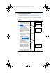
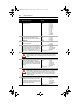
11 [DPI I/O Config]
I/O that is transferred through the adapter.
Default: xxx0 0001
Bit Values: 0 = I/O disabled
1 = I/O enabled
Type: Read/Write
Reset Required: Yes
Bit Definitions
0 = Cmd/Ref
1 = Datalink A
2 = Datalink B
3 = Datalink C
4 = Datalink D
5 = Not Used
6 = Not Used
7 = Not Used
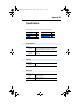
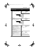
12 [DPI I/O Active]
I/O that the adapter is actively transmitting. The
value of this parameter will usually be equal to the
value of Parameter 11- DPI I/O Config.
Default: xxx0 0001
Bit Values: 0 = I/O disabled
1 = I/O enabled
Type: Read Only
Bit Definitions
0 = Cmd/Ref
1 = Datalink A
2 = Datalink B
3 = Datalink C
4 = Datalink D
5 = Not Used
6 = Not Used
7 = Not Used
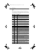
13 [Flt Cfg Logic]
Sets the Logic Command data that is sent to the
drive if any of the following is true:
•
Parameter 09 - [Comm Flt Action] is set to
Send Flt Cfg and communications are
disrupted.
•
Parameter 10 - [Idle Fault Action] is set to
Send Flt Cfg and the scanner is put into
Program mode.
The bit definitions will depend on the product to
which the adapter is connected.
Default: 0000 0000 0000 0000
Minimum: 0000 0000 0000 0000
Maximum: 1111 1111 1111 1111
Type: Read/Write
Reset Required: No
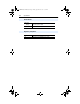
14 [Flt Cfg Ref]
Sets the Reference data that is sent to the drive if
any of the following is true:
•
Parameter 09- [Comm Flt Action] is set to
Send Flt Cfg and communications are
disrupted.
•
Parameter 10 - [Idle Flt Action] is set to Send
Flt Cfg and the scanner is put into Program
mode.
Default: 0
Minimum: 0
Maximum: 4294967295
Type: Read/Write
Reset Required: No
Important: If the drive uses a 16-bit
Reference, the most significant word of this
value must be set to zero (0) or a fault will
occur.
Parameter
No. Name and Description Details
Bit
Default
10000xxx
01234576
Bit
Default
10000xxx
01234576
20COMM-UM006A-EN-P.book Page 3 Friday, September 28, 2001 10:43 AM