
User guide

5-10 Using I/O Messaging
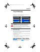
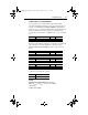
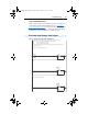
Figure 5.4 Example SLC Ladder Logic - Main Program (Continued)
For Ladder 3 Station 1 Drive Logic, see Figure 5.4 Example SLC Ladder
- Station 1 Program.
For Ladder 4 Station 2 Drive Logic, see Figure 5.6
Example SLC Ladder
- Station 2 Program.
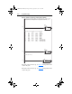
Profibus scanners vary from manufacturer to manufacturer in how the bytes are ordered in a word. For example, some Profibus
scanners operate with high & low bytes swapped (the value "1234" is represented as "3412"). The READ data is copied into
N10: and the bytes are reversed in the SWP instruction below so a value such as "3412" is viewed as "1234".
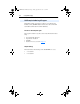
0003
COP
Copy File
Source #N9:0
Dest #N10:0
Length 28
COP
Station 1
Logic Status
File N10: contains the actual read data that can be used elsewhere in the ladder program.
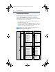
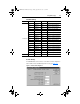
Station 1 Station 2 Description
M1:1.0 (N10:0) M1:1.14 (N10:14) Logic Status
M1:1.1 (N10:1) M1:1.15 (N10:15) Speed Feedback
M1:1.2 (N10:2) M1:1.16 (N10:16) Datalink A1
M1:1.3 (N10:3) M1:1.17 (N10:17) Datalink A2
M1:1.4 (N10:4) M1:1.18 (N10:18) Datalink B1
M1:1.5 (N10:5) M1:1.19 (N10:19) Datalink B2
M1:1.6 (N10:6) M1:1.20 (N10:20) Datalink C1
M1:1.7 (N10:7) M1:1.21 (N10:21) Datalink C2
M1:1.8 (N10:8) M1:1.22 (N10:22) Datalink D1
M1:1.9 (N10:9) M1:1.23 (N10:23) Datalink D2
M1:1.10 (N10:10) M1:1.24 (N10:24) Parameter Protocol Word #1
M1:1.11 (N10:11) M1:1.25 (N10:25) Parameter Protocol Word #2
M1:1.12 (N10:12) M1:1.26 (N10:26) Parameter Protocol Word #3
M1:1.13 (N10:13) M1:1.27 (N10:27) Parameter Protocol Word #4
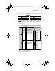
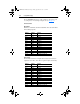
0004
SWP
Swap
Source #N10:0
Length 28
SWP
Station 1
Logic Status
Execute LAD 3 - Station 1 Drive Logic
0005
JSR
Jump To Subroutine
SBR File Number U:3
JSR
20COMM-UM006A-EN-P.book Page 10 Friday, September 28, 2001 10:43 AM