
User guide


Configuring the Adapter 3-5
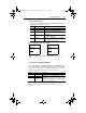
To change the fault action
• Set the values of Parameters 9 - [Comm Flt Action] and 10 - [Idle
Flt Action] to the desired responses:
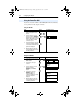
Figure 3.3 Fault Action Screens on an LCD HIM
Changes to these parameters take effect immediately. A reset is not
required.
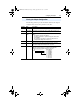
To set the fault configuration parameters
If you set Parameter 9 - [Comm Flt Action], or 10 - [Idle Flt Action]
to the “Send Flt Cfg,” the values in the following parameters are sent to
the drive after a communications fault and/or idle fault occurs. You must
set these parameters to values required by your application.
Changes to these parameters take effect immediately. A reset is not
required.
Value Action Description
0 Fault (default) The drive is faulted and stopped. (Default)
1 Stop The drive is stopped, but not faulted.
2 Zero Data The drive is sent 0 for output data after a
communications disruption. This does not
command a stop.
3 Hold Last The drive continues in its present state after a
communications disruption.
4 Send Flt Cfg The drive is sent the data that you set in the fault
configuration parameters (Parameters 13 - [Flt Cfg
Logic] through 22 - [Flt Cfg D2 In]).
Number Name Description
13 Flt Cfg Logic A 16-bit value sent to the drive for Logic Command.
14 Flt Cfg Ref A 32-bit value (0 – 4294967295) sent to the drive as a
Reference or datalink.
Important: If the drive uses a 16-bit Reference or 16-bit
Datalinks, the most significant word of the value must be
set to zero (0) or a fault will occur.
15 – 22 Flt Cfg x1 In or
Flt Cfg x2 In
Port 5 Device
20-COMM-P
Parameter #: 9
Comm Flt Action
0
Fault
Port 5 Device
20-COMM-P
Parameter #: 10
Idle Flt Action
0
Fault
20COMM-UM006A-EN-P.book Page 5 Friday, September 28, 2001 10:43 AM