
User guide

2-4 Installing the Adapter
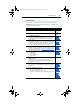
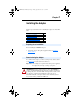
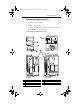
Figure 2.4 20-COMM-P DB-9 pin layout
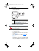
5. Connect the PROFIBUS cable to the adapter, and secure it with the
two screws on the connector. (See Figure 2.6
.)
Note: The screws on some connectors tie the Profibus cable ground/
shield to the metal of the socket. In some cases, Profibus will not
operate correctly without this connector.
Termination
The first and last node on the PROFIBUS network needs to be
terminated by using a PROFIBUS connector with terminating resistors.
Some connector manufacturers offer standard terminating connectors,
such as the yellow ERNI Profibus termination vertical connector (Part #
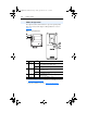
103659). Standard Profibus node connectors, such as the Phoenix
Subcon Plus M1 (Part #2761826), can be configured as a terminating
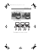
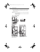
connector by adding resistors (See Figure 2.5
.)
Figure 2.5 Phoenix Subcon Plus M1 connection for terminating resistors
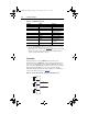
Terminal Signal Function
Housing Shield
1 Not connected
2 Not connected
3 B-LINE Positive RxD/TxD, according
to RS485 specification
4 RTS Request to send
5 GND BUS Isolated GND from bus
6 +5V BUS Isolated +5V from bus
7 Not connected
8 A-LINE Negative RxD/TxD
according to RS485
specification
9 Not connected
6
3
8
5
390
220
390
Ω
Ω
Ω
B
A
20COMM-UM006A-EN-P.book Page 4 Friday, September 28, 2001 10:43 AM