20COMM-UM006A-EN-P.book Page 1 Friday, September 28, 2001 10:43 AM PROFIBUS Adapter 20-COMM-P FRN 1.
0COMM-UM006A-EN-P.book Page 2 Friday, September 28, 2001 10:43 AM Important User Information Solid state equipment has operational characteristics differing from those of electromechanical equipment. “Safety Guidelines for the Application, Installation and Maintenance of Solid State Controls” (Publication SGI-1.1) describes some important differences between solid state equipment and hard-wired electromechanical devices.
20COMM-UM006A-EN-P.book Page i Friday, September 28, 2001 10:43 AM Table of Contents Table of Contents Preface About This Manual Related Documentation . . . . . . . . . . . . . . . . . . . . . . . . . . . . . P-1 Conventions Used in this Manual . . . . . . . . . . . . . . . . . . . . . P-2 Rockwell Automation Support. . . . . . . . . . . . . . . . . . . . . . . . P-2 Chapter 1 Getting Started Components . . . . . . . . . . . . . . . . . . . . . . . . . . . . . . . . . . . . . . Features . . . . . . . .
20COMM-UM006A-EN-P.book Page ii Friday, September 28, 2001 10:43 AM ii Table of Contents Chapter 5 Using I/O Messaging About I/O Messaging . . . . . . . . . . . . . . . . . . . . . . . . . . . . . . . 5-1 Understanding the I/O Image. . . . . . . . . . . . . . . . . . . . . . . . . 5-2 Using Logic Command/Status . . . . . . . . . . . . . . . . . . . . . . . . 5-4 Using Reference/Feedback . . . . . . . . . . . . . . . . . . . . . . . . . . 5-4 Using Datalinks . . . . . . . . . . . . . . . . . . . . . . .
20COMM-UM006A-EN-P.book Page 1 Friday, September 28, 2001 10:43 AM Preface About This Manual Topic Related Documentation Conventions Used in this Manual Rockwell Automation Support Page P-1 P-2 P-2 Related Documentation For: DriveExplorer™ DriveExecutive HIM PowerFlex™ 70 Drive PowerFlex 700 Drive Scanner SLC SLC Refer to: DriveExplorer Getting Results Manual Online Help (installed with the software) www.ab.
20COMM-UM006A-EN-P.book Page 2 Friday, September 28, 2001 10:43 AM P-2 About This Manual Conventions Used in this Manual The following conventions are used throughout this manual: • • • • Parameter names are shown in the following format Parameter xxx - [*]. The xxx represents the parameter number. The * represents the parameter name. For example Parameter 01 - [DPI Port]. Menu commands are shown in bold type face and follow the format Menu > Command.
20COMM-UM006A-EN-P.book Page 3 Friday, September 28, 2001 10:43 AM About This Manual U.S. Allen-Bradley Drives Technical Support: E-mail: support@drives.ra.rockwell.com Tel: (1) 262.512.8176 Fax: (1) 262.512.2222 Online: www.ab.com/support/abdrives UK Customer Support Center: E-mail: esupport2@ra.rockwell.com Tel: +44 (0) 870 2411802 Fax: +44 (0) 1908 838804 German Customer Service Center: E-mail: ragermany-csc@ra.rockwell.
20COMM-UM006A-EN-P.
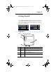
20COMM-UM006A-EN-P.book Page 1 Friday, September 28, 2001 10:43 AM Chapter 1 Getting Started The 20-COMM-P PROFIBUS adapter is an embedded communication option for any one drive in the PowerFlex family. It can also be used with other Allen-Bradley products implementing DPI™, a functional enhancement to SCANport™. Topic Components Features Compatible Products Required Equipment Page 1-1 1-2 1-2 1-3 Topic Safety Precautions Quick Start Modes of Operation Page 1-4 1-5 1-6 Components Figure 1.
20COMM-UM006A-EN-P.book Page 2 Friday, September 28, 2001 10:43 AM 1-2 Getting Started Features The PROFIBUS adapter features the following: • • • • • • • • The adapter is mounted in the PowerFlex drive. It receives the required power from the drive. Switches let you set a node address before applying power to the PowerFlex drive. Alternatively, you can disable the switches and use parameters to configure this feature. Captive screws are used to secure the adapter to the drive.
20COMM-UM006A-EN-P.book Page 3 Friday, September 28, 2001 10:43 AM Getting Started 1-3 Required Equipment Equipment Shipped with the Adapter When you unpack the adapter, verify that the package includes: ❑ ❑ ❑ ❑ ❑ One PROFIBUS adapter A 2.54 cm (1 in.) and a 15.24 cm (6 in.
20COMM-UM006A-EN-P.book Page 4 Friday, September 28, 2001 10:43 AM Getting Started 1-4 Safety Precautions Please read the following safety precautions carefully . ! ! ! ! ! ! ! ATTENTION: Risk of injury or equipment damage exists. Only personnel familiar with drive and power products and the associated machinery should plan or implement the installation, start-up, configuration, and subsequent maintenance of the product using a PROFIBUS adapter.
20COMM-UM006A-EN-P.book Page 5 Friday, September 28, 2001 10:43 AM Getting Started 1-5 Quick Start This section is designed to help experienced users start using the PROFIBUS adapter. If you are unsure about how to complete a step, refer to the referenced chapter. Step 1 Review the safety precautions for the adapter. 2 3 4 5 6 7 8 9 Refer to Throughout This Manual Verify that the PowerFlex drive is properly installed. Drive User Manual Commission the adapter.
20COMM-UM006A-EN-P.book Page 6 Friday, September 28, 2001 10:43 AM 1-6 Getting Started Modes of Operation The adapter uses three status indicators to report its operating status. They can be viewed on the adapter or through the drive cover. See Figure 1.2. Figure 1.2 Status Indicators ➊ ➋ ➌ PWR STS PORT MOD NET A NET B # ➊ ➋ ➌ ➍ (1) ➊ ➋ ➌ ➍ Status Status(1) Description Indicator PORT Green Normal Operation. The adapter is properly connected and is communicating with the drive.
20COMM-UM006A-EN-P.book Page 1 Friday, September 28, 2001 10:43 AM Chapter 2 Installing the Adapter Chapter 2 provides instructions for installing the adapter on a PowerFlex drive. Topic Preparing for an Installation Commissioning the Adapter Connecting the Adapter to the Network Connecting the Adapter to the Drive Applying Power Page 2-1 2-1 2-2 2-5 2-7 Preparing for an Installation Before installing the PROFIBUS adapter: • Verify that you have all required equipment.
20COMM-UM006A-EN-P.book Page 2 Friday, September 28, 2001 10:43 AM 2-2 Installing the Adapter 1. Set the node address switches. Figure 2.1 Setting the Node Address 2 2 3 4 1 0 5 9 6 8 Tens Digit Setting 0-99 7 3 4 1 0 5 9 6 8 7 Ones Digit Description Node address used by the adapter if switches are enabled. The default switch setting is 05. Important: If the address switch is set to “00”, the adapter will use the setting of Parameter 03 - [P-DP Addr Cfg] for the node address.
20COMM-UM006A-EN-P.book Page 3 Friday, September 28, 2001 10:43 AM Installing the Adapter Figure 2.2 ERNI and Phoenix Subcon connectors Phoenix Subcon Plus 1M Connector ERNI Connector Figure 2.3 Network Wiring Diagram B A B A B A B A B A B A Only use cable that conforms to PROFIBUS cable standards. Belden #3079A PROFIBUS cable or equivalent is recommended.
20COMM-UM006A-EN-P.book Page 4 Friday, September 28, 2001 10:43 AM 2-4 Installing the Adapter Figure 2.4 20-COMM-P DB-9 pin layout Terminal Housing 1 2 3 Signal Shield Not connected Not connected B-LINE 4 5 6 7 8 RTS GND BUS +5V BUS Not connected A-LINE 9 Not connected Function Positive RxD/TxD, according to RS485 specification Request to send Isolated GND from bus Isolated +5V from bus Negative RxD/TxD according to RS485 specification 5.
20COMM-UM006A-EN-P.book Page 5 Friday, September 28, 2001 10:43 AM Installing the Adapter 2-5 Connecting the Adapter to the Drive 1. Remove power from the drive. 2. Use static control precautions. 3. Connect the Internal Interface cable to the DPI port on the drive and then to the DPI connector on the adapter. Figure 2.
COMM-UM006A-EN-P.book Page 6 Friday, September 28, 2001 10:43 AM 2-6 Installing the Adapter 4. Fold the Internal Interface cable behind the adapter and mount the adapter on the drive using the four captive screws to secure and ground it to the drive. Important: On a PowerFlex 70 drive, the screw in the lower right hole grounds the adapter. On a PowerFlex 700 drive, the screw in the lower left hole grounds the adapter. Figure 2.
20COMM-UM006A-EN-P.book Page 7 Friday, September 28, 2001 10:43 AM Installing the Adapter 2-7 Applying Power ! ATTENTION: Risk of equipment damage, injury, or death exists. Unpredictable operation may occur if parameter settings and switch settings are not compatible with your application. Verify that settings are compatible with your application before applying power to the drive. 1. Verify that the adapter will have a unique address on the network.
20COMM-UM006A-EN-P.
20COMM-UM006A-EN-P.book Page 1 Friday, September 28, 2001 10:43 AM Chapter 3 Configuring the Adapter Chapter 3 provides instructions and information for setting the parameters in the adapter. Topic Configuration Tools Using the PowerFlex HIM Setting the Node Address Setting the I/O Configuration Page 3-1 3-2 3-3 3-3 Topic Setting a Fault Action Resetting the Adapter Viewing the Adapter Configuration Page 3-4 3-6 3-7 For a complete list of parameters, refer to Appendix B, Adapter Parameters.
20COMM-UM006A-EN-P.book Page 2 Friday, September 28, 2001 10:43 AM 3-2 Configuring the Adapter Using the PowerFlex HIM If your drive has either an LED or LCD HIM (Human Interface Module), access parameters in the adapter as follows: Using an LED HIM Step 1. Press the ALT and then Sel (Device) to display the Device Screen. 2. Press the Up Arrow or Down Arrow to scroll to the PROFIBUS adapter. Letters represent files in the drive, and numbers represent ports. The adapter is usually connected to port 5.
20COMM-UM006A-EN-P.book Page 3 Friday, September 28, 2001 10:43 AM Configuring the Adapter 3-3 Setting the Node Address If the node address switches are set to “00”, the value of Parameter 03 [P-DP Addr Cfg] determines the node address. 1. Set the value of Parameter 03 - [P-DP Addr Cfg] to a unique node address. Figure 3.1 PROFIBUS Node Address Screen on an LCD HIM Default = 01 Port 5 Device 20-COMM-P Parameter #: 3 P-DP Addr Cfg 01 0 <> 126 2. Reset the adapter.
20COMM-UM006A-EN-P.book Page 4 Friday, September 28, 2001 10:43 AM 3-4 Configuring the Adapter 2. If Logic Command/Reference is enabled (default), configure the parameters in the drive to accept the Logic Command and Reference from the adapter. For example, set Parameter 90 - [Speed Ref A Sel] in a PowerFlex 70 or 700 drive to “DPI Port 5” so that the drive uses the Reference from the adapter.
20COMM-UM006A-EN-P.book Page 5 Friday, September 28, 2001 10:43 AM Configuring the Adapter 3-5 To change the fault action • Set the values of Parameters 9 - [Comm Flt Action] and 10 - [Idle Flt Action] to the desired responses: Value 0 1 2 Action Fault (default) Stop Zero Data 3 Hold Last 4 Send Flt Cfg Description The drive is faulted and stopped. (Default) The drive is stopped, but not faulted. The drive is sent 0 for output data after a communications disruption. This does not command a stop.
20COMM-UM006A-EN-P.book Page 6 Friday, September 28, 2001 10:43 AM 3-6 Configuring the Adapter Resetting the Adapter Changes to switch settings or some adapter parameters require that you reset the adapter before the new settings take effect. You can reset the adapter by cycling power to the drive or by using the following parameter: ! ATTENTION: Risk of injury or equipment damage exists. If the adapter is transmitting control I/O to the drive, the drive may fault when you reset the adapter.
20COMM-UM006A-EN-P.book Page 7 Friday, September 28, 2001 10:43 AM Configuring the Adapter 3-7 Viewing the Adapter Configuration The following parameters provide information about how the adapter is configured. You can view these parameters at any time. Number 01 02 04 06 07 12 Name DPI Port Description The port on the drive to which the adapter is connected. Usually, it is port 5. DPI Data Rate The data rate used by DPI in the drive. It will be either 125 kbps or 500 kbps.
20COMM-UM006A-EN-P.
20COMM-UM006A-EN-P.book Page 1 Friday, September 28, 2001 10:43 AM Chapter 4 Configuring the Profibus Scanner Profibus scanners are available from several manufacturers, including SST. Chapter 4 provides instructions on how to utilize the SST Profibus configuration software tool to: • • Install the 20-COMM-P GSD file in the software tool library Configure the SST-PFB-SLC Profibus Scanner.
20COMM-UM006A-EN-P.book Page 2 Friday, September 28, 2001 10:43 AM 4-2 Configuring the Profibus Scanner Figure 4.1 Example Profibus Network COMM LED SYS LED Config Port Front Label Profibus Port Station 0 PowerFlex 70 Station 1 PowerFlex 70 Station 2 SST Profibus Configuration Software Tool SST Profibus scanners come with a software tool for configuring the scanner (See Figure 4.2.) Figure 4.
20COMM-UM006A-EN-P.book Page 3 Friday, September 28, 2001 10:43 AM Configuring the Profibus Scanner 4-3 Installing the 20-COMM-P GSD file in the software tool library GSD files are used by software tools to configure the network, i.e. to map and define the I/O in a Profibus scanner. A GSD file is required for each type of adapter on the network. For example: The 20-COMM-P GSD file is “A_B_0572.gsd” and a copy of the file is provided on a floppy disk with each 20-COMM-P.
20COMM-UM006A-EN-P.book Page 4 Friday, September 28, 2001 10:43 AM 4-4 Configuring the Profibus Scanner Figure 4.4 Add Profibus devices Applet window. 4. Find the directory location of the data file(s) you wish to add (typically, the source location is a floppy disk in drive A:). “A_B_0572.gsd” is the GSD file for the 20-COMM-P as shown in Figure 4.5. Figure 4.5 Adding the GSD file for the 20-COMM-P 5. Select “A_B_0572.gsd” for the 20-COMM-P and click Open.
20COMM-UM006A-EN-P.book Page 5 Friday, September 28, 2001 10:43 AM Configuring the Profibus Scanner 4-5 6. Click on the (+) sign of the Slaves folder as shown in Figure 4.6. Figure 4.6 Masters/Slaves Library window The software tool will automatically create an Allen-Bradley sub-folder (in the Slaves folder) if it does not already exist. The 20-COMM-P is now shown in the library and the software tool is now ready to configure a 20-COMM-P on a PROFIBUS network.
20COMM-UM006A-EN-P.book Page 6 Friday, September 28, 2001 10:43 AM 4-6 Configuring the Profibus Scanner 1. Click on the (+) sign of the Masters folder in the Library window to open the SST sub-folder. Available DP masters are displayed in this sub-folder. 2. Click on the (+) sign of the Slaves folder in the Library window and the Allen-Bradley sub-folder to display the available DP slaves or the 20-COMM-P slave. Refer to Figure 4.6. 3.
20COMM-UM006A-EN-P.book Page 7 Friday, September 28, 2001 10:43 AM Configuring the Profibus Scanner 4-7 6. Click on the COM Port tab. 7. Accept the settings in our example (COM1 on the PC @ 115200 bps baud rate), as shown in Figure 4.9. Figure 4.9 COM Port Default Settings 8. The scanner will appear in the network window as shown in Figure 4.10. Double-click on the scanner in the network window. Figure 4.10 Scanner Network window 9.
20COMM-UM006A-EN-P.book Page 8 Friday, September 28, 2001 10:43 AM 4-8 Configuring the Profibus Scanner Logic Command/ Status, Reference / Feedback, Datalinks and Parameter Access (explicit messaging) modules are added using the Modules tab. 10. Click on the Modules tab. Click Add to view the choice of modules. Figure 4.12 20-COMM-P Modules Tab In our example, Station 1 will be controlled using Logic Command / Status and Reference / Feedback.
20COMM-UM006A-EN-P.book Page 9 Friday, September 28, 2001 10:43 AM Configuring the Profibus Scanner 4-9 Figure 4.14 Modules: Ctrl/Stat & Ref/Fdbk Viewing Window Station 1 will be configured to use Datalinks A1 and A2. The PowerFlex 70 utilizes 16-bit Datalinks. 13. Click Add to continue adding modules. Select “Datalink A (2x2bytes)” and click OK. Figure 4.15 Add Modules: Datalink A Selection Window 14. The “Datalink A” module has now been added as shown in Figure 4.16.
20COMM-UM006A-EN-P.book Page 10 Friday, September 28, 2001 10:43 AM 4-10 Configuring the Profibus Scanner Figure 4.16 Modules: Datalink A Viewing Window Station 1 will also be configured to use Datalinks B1 and B2. The PowerFlex 70 utilizes 16-bit Datalinks. 15. Click Add to continue adding modules. Select “Datalink B (2x2 bytes)” and click OK. Figure 4.17 Add Modules: Datalink B Selection Window 16. The “Datalink B” module has now been added as shown in Figure 4.18.
20COMM-UM006A-EN-P.book Page 11 Friday, September 28, 2001 10:43 AM Configuring the Profibus Scanner 4-11 Figure 4.18 Modules: Datalink B Viewing Window Station 1 will also be configured to use Datalinks C1 and C2. The PowerFlex 70 utilizes 16-bit Datalinks. 17. Click Add to continue adding modules. Select “Datalink C (2x2 bytes)” and click OK. Figure 4.19 Add Modules: Datalink C Selection Window 18. The “Datalink C” module has now been added as shown in Figure 4.20.
20COMM-UM006A-EN-P.book Page 12 Friday, September 28, 2001 10:43 AM 4-12 Configuring the Profibus Scanner Figure 4.20 Modules: Datalink C Viewing Window Station 1 will also be configured to use Datalinks D1 and D2. The PowerFlex 70 utilizes 16-bit Datalinks. 19. Click Add to continue adding modules. Select “Datalink D (2x2 bytes)” and click OK. Figure 4.21 Add Modules: Datalink D Selection Window 20. The “Datalink D” module has now been added.
20COMM-UM006A-EN-P.book Page 13 Friday, September 28, 2001 10:43 AM Configuring the Profibus Scanner 4-13 21. Click Add to continue adding modules. Select “Parameter Access” and click OK. Figure 4.22 Add Modules: Parameter Access Selection Window 22. The “Parameter Access” module has now been added as shown in Figure 4.23. Figure 4.23 Modules: Parameter Access Viewing Window Settings can be chosen to map Station modules to SLC addresses. In our example M1/M0 files are used for Input / Output.
20COMM-UM006A-EN-P.book Page 14 Friday, September 28, 2001 10:43 AM 4-14 Configuring the Profibus Scanner 23. Click on the SLC Address tab as shown in Figure 4.24. Figure 4.24 SLC Address: M1/M0 (Ctrl/Stat & Ref/Fdbk) 24. Datalink A is at word 2 in the M1/M0 files as shown in Figure 4.25. Figure 4.
20COMM-UM006A-EN-P.book Page 15 Friday, September 28, 2001 10:43 AM Configuring the Profibus Scanner 4-15 25. Datalink B is at word 4 in the M1/M0 files as shown in Figure 4.26. Figure 4.26 SLC Address: M1/M0 (Datalink B) 26. Datalink C is at word 6 in the M1/M0 files as shown in Figure 4.27. Figure 4.
20COMM-UM006A-EN-P.book Page 16 Friday, September 28, 2001 10:43 AM 4-16 Configuring the Profibus Scanner 27. Datalink D is at word 8 in the M1/M0 files as shown in Figure 4.28. Figure 4.28 SLC Address: M1/M0 (Datalink D) 28. Parameter Access starts at word 10 in the M1/M0 files. Note that Parameter Access utilizes 4 words (10-13). Click OK when finished. Figure 4.29 SLC Address: M1/M0 (Parameter Access) 29. Station 1 is now displayed in the network window. Figure 4.
20COMM-UM006A-EN-P.book Page 17 Friday, September 28, 2001 10:43 AM Configuring the Profibus Scanner 4-17 Station 1 is configured as follows: Module Ctrl/Stat & Ref Fdbk Datalink A Datalink B Datalink C Datalink D Parameter Access M1/M0 Word 0 2 4 6 8 10 Note that Station 1 occupies 14 words (0-13). 30. The same steps for configuring Station 1 will be used for configuring Station 2. Refer to previous steps (starting at step #9, Page 4-7) for Configuring the SST-PFB-SLC Profibus Scanner-Station 2.
20COMM-UM006A-EN-P.book Page 18 Friday, September 28, 2001 10:43 AM 4-18 Configuring the Profibus Scanner Figure 4.32 Network window scanner selection 33. Click File and Save As from the tool bar, as a unique File Name. The configuration of the scanner is now complete. Note that cycling power to the scanner is recommended. (See Figure 4.33.) Figure 4.
20COMM-UM006A-EN-P.book Page 19 Friday, September 28, 2001 10:43 AM Configuring the Profibus Scanner GSD Diagnostic Messages In the case of invalid GSD module configuration, the peripheral will send one of the following messages: Fault No Ctrl/Stat & Ref/Fdbk Module used more than once Not supported module Description The Ctrl/Stat & Ref/Fdbk module must always be used and placed first in the configuration. A GSD module has been used more than once.
20COMM-UM006A-EN-P.
20COMM-UM006A-EN-P.book Page 1 Friday, September 28, 2001 10:43 AM Chapter 5 Using I/O Messaging Chapter 5 provides information and examples that explain how to use I/O Messaging to control a PowerFlex drive.
20COMM-UM006A-EN-P.book Page 2 Friday, September 28, 2001 10:43 AM 5-2 Using I/O Messaging Understanding the I/O Image The terms input and output are defined from scanner’s point of view. Therefore, Outputs are data that is output from the scanner and consumed by the PROFIBUS adapter. Inputs are status data that is produced by the adapter and consumed as input by the scanner.
20COMM-UM006A-EN-P.book Page 3 Friday, September 28, 2001 10:43 AM Using I/O Messaging 5-3 An image that uses 32-bit words for Reference and Datalinks would change the I/O image in Figure 5.1 as follows: Word 0 1-2 3-6 I/O Logic Command/Status Reference/Feedback Datalink A Word 7 - 10 11 - 14 15 - 18 I/O Datalink B Datalink C Datalink D Figure 5.2 illustrates an example of an I/O image that does not use all of the I/O data. Only the Logic Command/Reference and Datalink B are enabled.
20COMM-UM006A-EN-P.book Page 4 Friday, September 28, 2001 10:43 AM 5-4 Using I/O Messaging Using Logic Command/Status When enabled, the Logic Command/Status word is always word 0 in the I/O image. The Logic Command is a 16-bit word of control produced by the scanner and consumed by the adapter. The Logic Status is a 16-bit word of status produced by the adapter and consumed by the scanner.
20COMM-UM006A-EN-P.book Page 5 Friday, September 28, 2001 10:43 AM Using I/O Messaging 5-5 32-Bit Parameters using 16-Bit Datalinks To read (and/or write) a 32-bit parameter using 16-bit Datalinks, typically both Datalinks (A,B,C,D) are set to the 32-bit parameter. For example, to read Parameter 09 - [Elapsed MWh], both Datalink A1 and A2 are set to “9.” Datalink A1 will contain the least significant word (LSW) and Datalink A2 the most significant word (MSW). In this example, the parameter 9 value of 5.
20COMM-UM006A-EN-P.book Page 6 Friday, September 28, 2001 10:43 AM 5-6 Using I/O Messaging SLC Example Ladder Logic Program The Profibus example program uses a SLC processor with an SST Profibus scanner (SST-PFB-SLC) in the first slot of the rack and will work with PowerFlex 70 or PowerFlex 700 drives.
20COMM-UM006A-EN-P.book Page 7 Friday, September 28, 2001 10:43 AM Using I/O Messaging 5-7 Parameter Settings Device PowerFlex 70 20-COMM-P Parameter Name Value Description 90 Speed Ref A Sel 22 ‘DPI Port 5’ (20-COMM-P) 300 Data In A1 140 Points to Pr. 140 [Accel Time 1] 301 Data In A2 142 Points to Pr. 142 [Decel Time 1] 302 Data In B1 100 Points to Pr. 100 [Jog Speed] 303 Data In B2 155 Points to Pr. 155 [Stop Mode A] 304 Data In C1 101 Points to Pr.
20COMM-UM006A-EN-P.book Page 8 Friday, September 28, 2001 10:43 AM 5-8 Using I/O Messaging The two PROFIBUS adapters are setup as Station 1 and Station 2, and are configured as 14 words input & output each (See Chapter 4.) SLC Data Table Read Data File N10: contains the actual read data that can be used elsewhere in the ladder program.
20COMM-UM006A-EN-P.book Page 9 Friday, September 28, 2001 10:43 AM Using I/O Messaging 5-9 Logic Command/Status Words These examples use the Logic Command word and Logic Status word for PowerFlex 70 and PowerFlex 700 drives. Refer to Appendix C, Logic Command/Status Words for more information. The definition of the bits in these words may vary if you are using a different DPI Host product. Refer to the documentation for your Host product. SLC Ladder Logic Example - Main Program Figure 5.
20COMM-UM006A-EN-P.book Page 10 Friday, September 28, 2001 10:43 AM 5-10 Using I/O Messaging Figure 5.4 Example SLC Ladder Logic - Main Program (Continued) Profibus scanners vary from manufacturer to manufacturer in how the bytes are ordered in a word. For example, some Profibus scanners operate with high & low bytes swapped (the value "1234" is represented as "3412"). The READ data is copied into N10: and the bytes are reversed in the SWP instruction below so a value such as "3412" is viewed as "1234".
20COMM-UM006A-EN-P.book Page 11 Friday, September 28, 2001 10:43 AM Using I/O Messaging 5-11 Figure 5.4 Example SLC Ladder Logic - Main Program (Continued) Execute LAD 4 - Station 2 Drive Logic JSR Jump To Subroutine SBR File Number 0006 U:4 The Profibus scanner is configured for 28 bytes (14 words) of outputs for each drive. Two drives require 48 bytes (28 words). Station 1 M0:1.0 M0:1.1 M0:1.2 M0:1.3 M0:1.4 M0:1.5 M0:1.6 M0:1.7 M0:1.8 M0:1.9 M0:1.10 M0:1.11 M0:1.12 M0:1.
20COMM-UM006A-EN-P.book Page 12 Friday, September 28, 2001 10:43 AM 5-12 Using I/O Messaging Figure 5.5 SLC Ladder Logic Example - Main Program Write the drives data to the Profibus scanner. 0009 0010 SST Scanner Write Data Word 0 COP Copy File Source Dest Length #N21:0 #M0:1.
20COMM-UM006A-EN-P.book Page 13 Friday, September 28, 2001 10:43 AM Using I/O Messaging 5-13 SLC Ladder Logic Example - Station 1 Program Figure 5.6 Example SLC Ladder Logic - Station 1 Program Controlling the Logic Command word in the drive. B3:20 /* bits are controlled elsewhere in the user program.
20COMM-UM006A-EN-P.book Page 14 Friday, September 28, 2001 10:43 AM 5-14 Using I/O Messaging Figure 5.6 Example SLC Ladder Logic - Station 1 Program (Continued) Station 1 Datalink A1 Datalink A1 (Pr. 300) set to Acceleration Time 1 (Pr. 140). N19:2 is controlled elsewhere in the user program. Station 1 Datalink A1 Write MOV Move Source 0007 Dest N19:2 50< N20:2 50< Station 1 Datalink A2 Datalink A2 (Pr. 301) set to Deceleration Time 1 (Pr. 142). N19:3 is controlled elsewhere in the user program.
20COMM-UM006A-EN-P.book Page 15 Friday, September 28, 2001 10:43 AM Using I/O Messaging 5-15 Figure 5.6 Example SLC Ladder Logic - Station 1 Program (Continued) Station 1 Datalink B2 Datalink B2 (Pr. 303) set to Stop Mode A (Pr. 155). N19:5 is controlled elsewhere in the user program. Station 1 Datalink B2 Write MOV Move Source 0010 Dest N19:5 1< N20:5 1< Station 1 Datalink C1 Datalink C1 (Pr. 304) set to Preset Speed 1 (Pr. 101). N19:6 is controlled elsewhere in the user program.
20COMM-UM006A-EN-P.book Page 16 Friday, September 28, 2001 10:43 AM 5-16 Using I/O Messaging Figure 5.6 Example SLC Ladder Logic - Station 1 Program (Continued) Station 1 Datalink D1 Datalink D1 (Pr. 306) set to Preset Speed 3 (Pr. 103). N19:8 is controlled elsewhere in the user program. Station 1 Datalink D1 Write MOV Move Source 0013 Dest N19:8 300< N20:8 300< Station 1 Datalink D2 Datalink D2 (Pr. 307) set to Preset Speed 4 (Pr. 104). N19:9 is controlled elsewhere in the user program.
20COMM-UM006A-EN-P.book Page 17 Friday, September 28, 2001 10:43 AM Using I/O Messaging 5-17 SLC Ladder Logic Example - Station 2 Program Figure 5.7 Example SLC Ladder Logic - Station 2 Program Controlling the Logic Command word in the drive. B3:21 /* bits are controlled elsewhere in the user program.
20COMM-UM006A-EN-P.book Page 18 Friday, September 28, 2001 10:43 AM 5-18 Using I/O Messaging Figure 5.7 Example SLC Ladder Logic - Station 2 Program (Continued) Station 2 Speed Reference PowerFlex 70 Speed Ref A Sel (Pr.90) needs to be set to 'DPI Port 5'. N19:15 is controlled elsewhere in the user program. Station 2 Speed Reference Write MOV Move Source N19:15 8192 < Dest N20:15 8192 < 0006 Station 2 Datalink A1 Datalink A1 (Pr. 300) set to Acceleration Time 1 (Pr. 140).
20COMM-UM006A-EN-P.book Page 19 Friday, September 28, 2001 10:43 AM Using I/O Messaging Figure 5.7 Example SLC Ladder Logic - Station 2 Program (Continued) Station 2 Datalink B1 Datalink B1 (Pr. 302) set to Jog Speed (Pr. 100). N19:18 is controlled elsewhere in the user program. Station 2 Datalink B1 Write MOV Move Source 0009 Dest N19:18 100< N20:18 100< Station 2 Datalink B2 Datalink B2 (Pr. 303) set to Stop Mode A (Pr. 155). N19:19 is controlled elsewhere in the user program.
20COMM-UM006A-EN-P.book Page 20 Friday, September 28, 2001 10:43 AM 5-20 Using I/O Messaging Figure 5.7 Example SLC Ladder Logic - Station 2 Program (Continued) Station 2 Datalink C2 Datalink C2 (Pr. 305) set to Preset Speed 2 (Pr. 102). N19:21 is controlled elsewhere in the user program. Station 2 Datalink C2 Write MOV Move Source 0012 Dest N19:21 200< N20:21 200< Station 2 Datalink D1 Datalink D1 (Pr. 306) set to Preset Speed 3 (Pr. 103). N19:22 is controlled elsewhere in the user program.
20COMM-UM006A-EN-P.book Page 1 Friday, September 28, 2001 10:43 AM Chapter 6 Using Explicit Messaging (Parameter Protocol) Chapter 6 provides information and examples that explain how to use Explicit Messaging to monitor and configure the adapter and connected PowerFlex drive, as well as other peripherals.
20COMM-UM006A-EN-P.book Page 2 Friday, September 28, 2001 10:43 AM 6-2 Using Explicit Messaging (Parameter Protocol) To be able to use the parameter protocols in the 20-COMM-P, the Parameter Access module in the GSD file must be added to the master configuration when configuring the network. Refer to step #21, Page 4-13 to view the procedure for adding the “Parameter Access” module to a configuration.
20COMM-UM006A-EN-P.book Page 3 Friday, September 28, 2001 10:43 AM Using Explicit Messaging (Parameter Protocol) 6-3 Event 1. You format the required data and set up the ladder logic program to send an Explicit Message request to the scanner module (download). 2. The scanner module transmits the Explicit Message Request to the slave device over the PROFIBUS network. 3. The slave device transmits the Explicit Message Response back to the master. 4. The controller retrieves the Explicit Message Response.
20COMM-UM006A-EN-P.book Page 4 Friday, September 28, 2001 10:43 AM 6-4 Using Explicit Messaging (Parameter Protocol) Refer to Page 6-4 and Page 6-5 for a description of the data that is required in each word. Parameter Message Request Word 1 2 3 4 Description PNU - Parameter Number (Bit 0-10) The parameter number determines which parameter to access, in the selected peripheral. Parameters 1-1023 can be accessed. Parameter numbers 1024 - 2048 are used to access the fault object.
20COMM-UM006A-EN-P.book Page 5 Friday, September 28, 2001 10:43 AM Using Explicit Messaging (Parameter Protocol) 6-5 Parameter Message Response Word 1 2 3 4 Description PNU - Parameter Number (Bit 0-10) Requested parameter number. SPM (Bit 11) Reserved - is always set to 0. RC - Response Code (Bit 12-15) One of the following codes will be sent: 0 = No request 1 = Transfer parameter value (8-bit & 16-bit word) 2 = Transfer parameter value (32-bit word) 3-6 = Reserved 7 = Request rejected.
20COMM-UM006A-EN-P.book Page 6 Friday, September 28, 2001 10:43 AM 6-6 Using Explicit Messaging (Parameter Protocol) Parameter Protocol Examples Read Examples Figure 6.
20COMM-UM006A-EN-P.book Page 7 Friday, September 28, 2001 10:43 AM Using Explicit Messaging (Parameter Protocol) 6-7 tion crip Des Valu e (he x ) Par . Wo Acces rd s SLC Add ress Mes sag e Reading Parameter 140 [Accel Time 1] from the PowerFlex 70 (DPI Port 0) Command N20:10 1 N20:11 2 0 1000 hex = Read 8C hex = 140 dec (Pr. 140) DPI Port 0 (DPI Host) N20:12 3 0 Not Used N20:13 4 0 Not Used N10:10 1 108C Transferring 16-bit parameter value ("1") Confirms Par.
20COMM-UM006A-EN-P.book Page 8 Friday, September 28, 2001 10:43 AM Using Explicit Messaging (Parameter Protocol) Command N20:10 1 N20:11 2 N20:12 3 Reply tion crip Des Valu e (he x) Par . Wo Acces rd s SLC Add re ss Reading Par. 244 [Fault 1 Time] from the PowerFlex 70 (DPI Port 0) Mes sag e 6-8 1000 hex = Read 10F4 F4 hex = 244 dec (Pr. 244) 0 DPI Port 0 (DPI Host) 0 Not Used 0 Not Used N20:13 4 N10:10 1 10F4 Transferring 16-bit parameter value ("1") Confirms Par.
20COMM-UM006A-EN-P.
20COMM-UM006A-EN-P.book Page 10 Friday, September 28, 2001 10:43 AM Using Explicit Messaging (Parameter Protocol) Command N20:10 1 Reply on Valu e Des crip ti (he x) ss Par . Ac c Wo rd ess SLC Add re Mes sag e Writing Parameter 9 [Comm Fault Action] to the 20-COMM-P on a PowerFlex 70 (DPI Port 5) 2000 hex = Change parameter value 8-bit/16-bit 9 hex = 9 dec (Pr.
20COMM-UM006A-EN-P.book Page 11 Friday, September 28, 2001 10:43 AM Using Explicit Messaging (Parameter Protocol) 6-11 SLC Ladder Example - Station 1 Parameter Protocol Figure 6.5 Example SLC Ladder Logic - Station 1 Parameter Protocol This section of the routine is only needed if the application needs to perform Parameter Protocol Reads or Writes to Station 1. On power-up, initialize the Parameter Protocol routine.
20COMM-UM006A-EN-P.book Page 12 Friday, September 28, 2001 10:43 AM 6-12 Using Explicit Messaging (Parameter Protocol) Figure 6.5 Example SLC Ladder Logic - Station 1 Parameter Protocol (Continued) N10:10 is the Station 1 Response Parameter Access Word 1. It is < > 0 when a message has been received in response to a message request. If the response is >= 7000 hex (28672 decimal), then the adapter is responding that an error has occurred.
20COMM-UM006A-EN-P.book Page 13 Friday, September 28, 2001 10:43 AM Using Explicit Messaging (Parameter Protocol) 6-13 SLC Ladder Example - Station 2 Parameter Protocol Figure 6.6 Example SLC Ladder Logic - Station 2 Parameter Protocol This section of the routine is only needed if the application needs to perform Parameter Protocol Reads or Writes to Station 2. Station 2 Par Prot Messaging Request B3:19 U 0 On power-up, initialize the Parameter Protocol routine.
20COMM-UM006A-EN-P.book Page 14 Friday, September 28, 2001 10:43 AM 6-14 Using Explicit Messaging (Parameter Protocol) Figure 6.6 Example SLC Ladder Logic - Station 2 Parameter Protocol (Continued) N10:24 is the Station 2 Response Parameter Access Word 1. It is < > 0 when a message has been received in response to a message request. If the response is >= 7000 hex (28672 decimal), then the adapter is responding that an error has occurred.
20COMM-UM006A-EN-P.
20COMM-UM006A-EN-P.
20COMM-UM006A-EN-P.book Page 1 Friday, September 28, 2001 10:43 AM Chapter 7 Troubleshooting Chapter 7 contains troubleshooting information. Topic Locating the Status Indicators PORT Status Indicator MOD Status Indicator Page 7-1 7-2 7-3 Topic NET A Status Indicator Adapter Diagnostic Items Viewing and Clearing Events Page 7-3 7-4 7-5 Locating the Status Indicators The PROFIBUS adapter has three status indicators. They can be viewed on the adapter or through the drive cover. (See Figure 7.1.
20COMM-UM006A-EN-P.book Page 2 Friday, September 28, 2001 10:43 AM 7-2 Troubleshooting ti PORT Status Indicator Status Off Flashing Red Solid Red Orange Flashing Green Solid Green Cause The adapter is not powered or is not connected properly to the drive. The adapter is not receiving a ping message from the drive. The drive has refused an I/O connection from the adapter. Corrective Action • Securely connect the adapter to the drive using the ribbon cable. • Apply power to the drive.
20COMM-UM006A-EN-P.book Page 3 Friday, September 28, 2001 10:43 AM Troubleshooting MOD Status Indicator Status Off Cause The adapter is not powered. Flashing Red The adapter has failed the firmware test. Solid Red Flashing Green The adapter has failed the hardware test. The adapter is operational but is not transferring I/O data. Solid Green The adapter is operational and transferring I/O data. Corrective Action • Securely connect the adapter to the PowerFlex drive using the ribbon cable.
20COMM-UM006A-EN-P.book Page 4 Friday, September 28, 2001 10:43 AM 7-4 Troubleshooting Adapter Diagnostic Items Adapter Diagnostic Items are viewable with DriveExplorer (version 2.01 or higher), DriveExecutive (version 1.01 or higher) or HIM (2.001) software. No.
20COMM-UM006A-EN-P.book Page 5 Friday, September 28, 2001 10:43 AM Troubleshooting 7-5 Viewing and Clearing Events The adapter maintains an event queue that reports the history of its actions. You can view the event queue using an LCD PowerFlex HIM, DriveExplorer (2.01 or higher) software, or DriveExecutive (1.01 or higher). Step Keys Viewing Events 1. Access parameters in the adapter. Refer to Using the PowerFlex HIM in Chapter 3. 2. Press the Up Arrow or Down Arrow to scroll to Diagnostics. 3.
20COMM-UM006A-EN-P.book Page 6 Friday, September 28, 2001 10:43 AM 7-6 Troubleshooting Events Many events in the Event queue occur under normal operation. If you encounter unexpected communications problems, the events may help you or Allen-Bradley personnel troubleshoot the problem.
20COMM-UM006A-EN-P.book Page 7 Friday, September 28, 2001 10:43 AM Troubleshooting Code 26 Event P-DP Offline 27 P-DP Idle 28 Language CRC Bad Description The PROFIBUS adapter has gone off-line the PROFIBUS network. The PROFIBUS adapter received a network clear from the PROFIBUS master. The language flash segment is corrupt - flash the adapter.
20COMM-UM006A-EN-P.
20COMM-UM006A-EN-P.book Page 1 Friday, September 28, 2001 10:43 AM Appendix A Specifications This chapter presents the specifications for the adapter. Topic Communications Electrical Mechanical Page A-1 A-1 A-1 Topic Page Environmental A-2 Regulatory Compliance A-2 Communications Network Protocol Data Rates Drive Protocol Data Rates PROFIBUS 9.6K, 19.2K, 45.45K, 93.75K, 187.5K, 500K, 1.5M, 3M, 6M, 12M. The adapter has auto baud rate detection.
20COMM-UM006A-EN-P.
20COMM-UM006A-EN-P.book Page 1 Friday, September 28, 2001 10:43 AM Appendix B Adapter Parameters Appendix B provides information about the PROFIBUS adapter parameters. Topic Page About Parameter Numbers B-1 Parameter List B-1 About Parameter Numbers The parameters in the adapter are numbered consecutively. However, depending on which configuration tool you use, they may have different numbers.
20COMM-UM006A-EN-P.book Page 2 Friday, September 28, 2001 10:43 AM B-2 Adapter Parameters Parameter No. Name and Description 05 [P-DP Rate Actual] PROFIBUS data rate. 06 07 08 [Ref/Fdbk Size] Size of the Reference/Feedback. The drive determines the size of the Reference/Feedback. N/A 0 = 9.6 K 1 = 19.2 K 2 = 45.45 K 3 = 93.75 K 4 = 187.5 K 5 = 500 K 6 = 1.
20COMM-UM006A-EN-P.book Page 3 Friday, September 28, 2001 10:43 AM Adapter Parameters Parameter No. Name and Description 11 [DPI I/O Config] I/O that is transferred through the adapter.
20COMM-UM006A-EN-P.book Page 4 Friday, September 28, 2001 10:43 AM B-4 Adapter Parameters Parameter No. Name and Description 15 [Flt Cfg A1] 16 [Flt Cfg A2] 17 [Flt Cfg B1] 18 [Flt Cfg B2] 19 [Flt Cfg C1] 20 [Flt Cfg C2] 21 [Flt Cfg D1] 22 [Flt Cfg D2] Sets the data that is sent to the Datalink in the drive if any of the following is true: • Parameter 09 - [Comm Flt Action] is set to Send Flt Cfg and the scanner is put into Program mode.
20COMM-UM006A-EN-P.
20COMM-UM006A-EN-P.
20COMM-UM006A-EN-P.book Page 1 Friday, September 28, 2001 10:43 AM Appendix C Logic Command/Status Words Appendix C provides the definitions of the Logic Command/Logic Status words that are used for some products that can be connected to the Profibus adapter. If you do not see the Logic Command/Logic Status for the product that you are using, refer to your product’s documentation.
20COMM-UM006A-EN-P.
20COMM-UM006A-EN-P.book Page 1 Friday, September 28, 2001 10:43 AM Glossary A Adapter Devices such as drives, controllers, and computers usually require an adapter to provide a communication interface between them and a network such as PROFIBUS. An adapter reads data on the network and transmits it to the connected device. It also reads data in the device and transmits it to the network. The 20-COMM-P PROFIBUS adapter is an adapter that connects, PowerFlex drives to a PROFIBUS network.
20COMM-UM006A-EN-P.book Page 2 Friday, September 28, 2001 10:43 AM Glossary-2 Datalinks A Datalink is a type of pointer used by some PowerFlex drives to transfer data to and from the controller. Datalinks allow specified parameter value(s) to be accessed or changed without using explicit messages. When enabled, each Datalink consumes either four bytes or eight bytes in both the input and output image table of the controller. The drive determines the size of Datalinks.
20COMM-UM006A-EN-P.book Page 3 Friday, September 28, 2001 10:43 AM Glossary-3 Fault Configuration When communications are disrupted (for example, a cable is disconnected), the adapter and PowerFlex drive can respond with a user-defined fault configuration. The user sets the data that is sent to the drive in the fault configuration parameters (Parameters 13 - [Flt Cfg Logic] through 22 - [Flt Cfg D2]).
20COMM-UM006A-EN-P.book Page 4 Friday, September 28, 2001 10:43 AM Glossary-4 I I/O Data I/O transmit time-critical data such as a Logic Command and Reference. The terms “input” and “output” are defined from the scanner’s point of view. Output is transmitted by the scanner and consumed by the adapter. Input is transmitted by the adapter and consumed by the scanner. L Logic Command/Logic Status The Logic Command is used to control the PowerFlex drive (e.g., start, stop, direction).
20COMM-UM006A-EN-P.book Page 5 Friday, September 28, 2001 10:43 AM Glossary-5 PowerFlex Drives The Allen-Bradley PowerFlex family of drives includes PowerFlex 70, PowerFlex 700, and PowerFlex 7000 drives. These drives can be used for applications ranging from 0.37 kW (0.5 HP) to 3,000 kW (4,000 HP). All PowerFlex drives implement DPI, allowing them to use the 20-COMM-P PROFIBUS adapter. This manual focuses on using the adapter with PowerFlex drives.
20COMM-UM006A-EN-P.book Page 6 Friday, September 28, 2001 10:43 AM Glossary-6 Z Zero Data When communications are disrupted (for example, a cable is disconnected), the adapter and drive can respond with zero data. Zero data results in the drive receiving zero as values for command data. If the drive was running and using the Reference from the adapter, it will stay running but at zero Reference.
20COMM-UM006A-EN-P.book Page 1 Friday, September 28, 2001 10:43 AM Allen-Bradley, ControlFLASH, DPI, DriveExplorer, DriveTools32, DriveTools 2000, DriveExecutive, PLC-5, PowerFlex, SCANport, and SLC are trademarks of Rockwell Automation. PROFIBUS is a trademark of the PROFIBUS Trade Organization. RSLogix is a trademark of Rockwell Software. Windows, Windows CE, Windows NT, and Microsoft are either registered trademarks or trademarks of Microsoft Corporation.
20COMM-UM006A-EN-P.
20COMM-UM006A-EN-P.
20COMM-UM006A-EN-P.
20COMM-UM006A-EN-P.
20COMM-UM006A-EN-P.
20COMM-UM006A-EN-P.book Page 1 Friday, September 28, 2001 10:43 AM Publication 20COMM-UM006A-EN-P - November, 2001 P/N 196064-P01 Copyright (C) 2001 Rockwell Automation. All rights reserved. Printed in USA.